Wireless Communication Links
The Wireless functionality adds radio links to Riverbed Modeler. Radio links exist as a function of dynamic conditions and so are not represented by objects. Instead they result from a dynamic evaluation by the Simulation Kernel. Radio links potentially allow all nodes in a model to communicate with each other, based on a dynamic evaluation.
Radio Links
A radio link might exist between any radio transmitter-receiver channel pair and is dynamically established during simulation. The possibility of a radio link between a transmitter channel and a receiver channel can be dependent on many physical characteristics of the components involved, as well as time-varying parameters. In simulations, parameters such as frequency band, modulation type, transmitter power, distance, and antenna directionality are commonly factored into the determination of whether a radio link exists at a particular time. Therefore, a radio link is not statically represented by an object, as are point-to-point and bus links.
Correspondingly, radio transmitter and receiver objects have a greater role in determining the behavior of a radio link. Unlike point-to-point and bus link objects which have attributes to specify the pipeline stages, a radio link is not an object and cannot provide those values. Therefore, the radio transmitter and receiver objects’ attributes identify the appropriate pipeline stage values that make up the transceiver pipeline, which performs the calculations required to determine when and if a packet is successfully received. For a full description of the Radio Transceiver Pipeline, refer to Chapter 10 “Radio Transceiver Pipeline” on page 263. The remainder of this section explains how the network-level objects (nodes and subnets) affect the default radio transceiver pipeline.
Because radio is a broadcast technology and depends on dynamically changing parameters, the transceiver pipeline must evaluate the possible connectivity between a transmitter channel and every receiver channel for each transmission. The network level characteristics factored into the default transceiver pipeline calculations are the source and destination sites’ locations, the distance between the sites, and the direction the radio signal travels from the source site to the destination site. If the sites are mobile or satellite sites, then these position-related parameters can change during simulation.
The locations of the sites are significant factors in a radio link, because the default transceiver pipeline computes whether the source site has direct line of sight to the destination node. Line of sight depends on where the sites are positioned relative to the earth. If the earth’s surface is between the two sites, then the sites are said to be occluded and the computation of the radio link is discontinued. If the earth is not between the two sites, then link closure is said to exist and the computation of the link continues. If you are using terrain modeling, link closure can be affected by terrain features such as hills, in addition to the earth’s curvature.
The distance between the sites determines the propagation delay and path loss of the radio signal. The default transceiver pipeline computes the propagation delay of the radio signal traveling from the source site to the destination site at the speed of light. The transceiver pipeline also models the weakening of the radio signal as it propagates from the source site. It is assumed that the path loss is directly related to the reciprocal of the distance squared. If you are using terrain modeling, atmospheric conditions and surface terrain can also affect propagation and path loss.
Figure 2: Locations of Source and Destination Nodes Affect Radio Link in Default Transceiver Pipeline
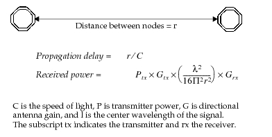
As a packet is sent from a radio transmitter or received by a radio receiver, the power of the radio signal can be influenced by antennas. In some directions, the signal level can be higher and in other directions, lower. The default transceiver pipeline takes this into account by determining the direction the radio signal travels from the source site to the destination site. As the radio signal radiates from the transmitter, the transceiver pipeline calculates the signal power out that direction of the antenna. If there is no antenna object attached to the transmitter in the site, the transceiver pipeline assumes that the signal power is equal in all directions. When the radio signal reaches the destination site, the transceiver pipeline also calculates the direction of the signal into the receiver’s antenna, if there is an antenna. The antenna can increase or decrease the signal received based on the incoming direction of the radio signal. As with the transmitter, if a receiver does not have an antenna object attached to it, the signal level is not adjusted.
The propagation delay and signal strength computations are important factors in determining when and if a packet arrives successfully at the destination site. The propagation delays of packets determine when the packets arrive and whether the packets collide. Collisions cause interference which is noise to the signal of a particular packet. With the signal strength and noise computed, the transceiver pipeline calculates the signal-to-noise ratio and from that the bit error rate and bit error count, which determines the acceptability of the packet. Packet format incompatibilities are also considered.
Radio Link Details
From the perspective of the modules within a node, radio links are used in the same manner as point-to-point and bus links. In other words, if a module wishes to send a packet via a radio link, it must send the packet to one of the input streams of a radio transmitter. The radio transmitter is then responsible for sending the packet to radio receivers in remote nodes. These radio receivers in turn issue correctly received packets on appropriate output streams.
Like a bus or point-to-point transmitter, a radio transmitter maintains a channel object for each of its input streams and each channel contains a queue where submitted packets wait for previous packets to complete transmission. However, whereas bus and point-to-point transmitter channels have primarily a logical significance, radio transmitter channels also have a physical significance that is described by an additional set of attributes. These additional attributes characterize the radio channel in terms of the frequency band it occupies, the power applied to transmissions, the data rate of transmission, and an optional code used to identify a spread spectrum sequence.
Radio channels are referred to by integer indices to establish a correspondence with the input and output streams they use. In other words, packets for channel n should be sent to input stream n; similarly, packets correctly received by a radio receiver on channel n are sent to a neighboring module using output stream n. However, the index-based correspondence does not necessarily hold across radio links. That is, a packet transmitted using channel n might be received on a channel with index other than n. This is because radio links are established between channels based on their attributes as opposed to their logical index. The actual establishment of a link is decided upon by user-definable radio link models and is dependent upon a number of transmitter and receiver attributes as well as other factors. For example, a simple link model might require only that the frequency bands of a transmitter channel and receiver channel overlap to establish a link; a link would exist regardless of whether the channels had the same index.
Figure 3: Radio Link Channel Correspondence
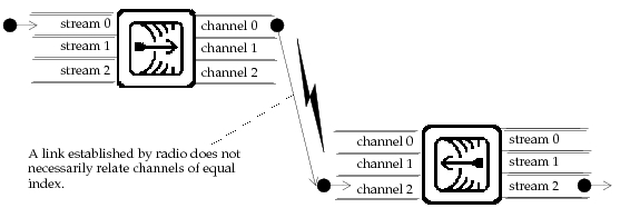
Like bus transmitters, radio transmitters transmit packets by broadcasting them. Therefore, packets are replicated for each selected destination to allow them to be evaluated and modified independently. Note that, unlike bus links, replication is on a per-channel basis at the destination, because a single packet can affect multiple channels within a radio receiver. Again, this is due to the fact that channels are compared on the basis of their physical characteristics, rather than their logical index values.
The eligible receivers of each radio transmitter are not necessarily known in advance, as in the usual case of a bus configuration. Instead, the existence and quality of each link is generally computed on a dynamic basis to reflect potentially changing conditions in the network. Important events, such as position changes and interference, can have a significant impact on the ability of a transmitter channel and a receiver channel to communicate, and these events might occur at any time. The detailed behavior and mechanics of radio transmissions are specified in a series of low-level radio models, referred to as pipeline stages. The theory and operation of radio pipeline stages are described in detail in Chapter 10 “Radio Transceiver Pipeline” on page 263.
In addition to the methods listed in Table 1, Riverbed Modeler users can apply the following methods to reduce the amount of time spent on pipeline calculations:
Table 3: Reducing Wireless Simulation Time (Advanced)
| To… | Refer to… |
|---|---|
| Dynamically control the number of receivers each transmitter tests | “Stage 0: Receiver Group” on page 268, for a description of the receiver group stage Chapter 16 “Radio Package” on page 1, for descriptions of Kernel Procedures for managing receiver groups |
| Customize the caching of pipeline calculation results | “Wireless Domain Editor” on page 251 for more information about defining new wireless domains “Default Models” on page 284, for how to replace pipeline stage calculations with default results |