Wireless Domains
As described in Wireless Communication Links, the Simulation Kernel must do many calculations for each packet sent across a radio link. These calculations are done for each channel that might be able to receive the transmitted packet. Wireless domains provide a way to reduce the number of calculations that must be done, thus reducing the time needed for a wireless simulation to run (at the cost of increased memory use).
A wireless domain defines a rectangular area that is subdivided into a logical grid of clusters. Each cluster represents an area in which any contained nodes are assumed to have the same characteristics (such as path loss) with respect to nodes in other clusters of the domain. The wireless domain saves selected results of the radio pipeline calculations and reuses them for future communications between the same clusters. The results that can be saved for reuse are:
- Channel match
- Closure
- Propagation delay
- Path loss
For example, consider the simple wireless domain with 6 clusters shown in the following figure. The first time node T1 (in cluster 5) communicates with a node in cluster 1 (either R1 or R2), the Simulation Kernel does the calculations for the full radio pipeline and saves some of the results in the cache of the wireless domain. Thereafter, each time T1 communicates with a node in cluster 1, the Simulation Kernel reuses the saved results for this path. (Note that the results apply to the path from cluster 5 to 1, not to specific nodes. If R3 is mobile and moves into cluster 1, node T1 can reuse the same saved results with it.)
Figure 4: Wireless Domain Example
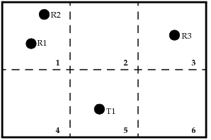
Note: Because clusters cannot overlap, a given position in a wireless domain can belong to at most one cluster. However, the area of a wireless domain might not be fully covered by clusters. Thus, a position might not belong to any cluster. The wireless domain model defines whether each position in a wireless domain maps to a cluster and, if so, to which one.
Although the technique of reusing certain pipeline stage calculations introduces some approximation into a simulation, it is small for well-chosen cluster sizes and does not affect simulation results appreciably.
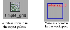
Figure 5: Wireless Domain Representations
Procedure 1: Adding a Wireless Domain to a Network Model
- Configure an object palette with the wireless domain models you want to use. (Riverbed Modeler includes some basic wireless domain models. Riverbed Modeler users can create their own models, as described in Chapter 9 “Wireless Domain Editor” on page 251.)
- Place a wireless domain object in the workspace and resize it to cover the area you want to include in the wireless domain.
- Set the attributes of the wireless domain object. These will vary depending on the wireless domain model being used. For more information about built-in attributes of wireless domain objects, see “Wireless Domain Object” on page 136.