Wireless Network Deployment Examples
Battlefield Network
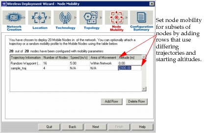
One potential use for the wireless network deployment wizard is to simulate the movement of mobile nodes in a battlefield network. You can create mobile nodes that have different trajectories and initial altitude, allowing you to simulate both ground and airborne troop movements. To create this example, we accepted all defaults except in regard to the Technology and Node Mobility screens, shown in Figure 26 and Figure 27.
Figure 26: Battlefield Network Example–Technology Specifications
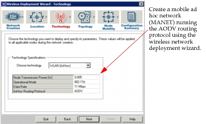
Figure 27: Battlefield Network Example–Node Mobility Specifications
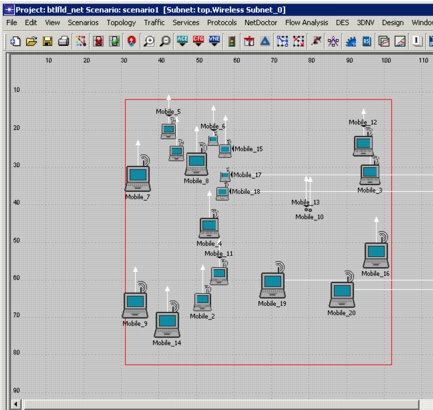
The following figure shows the battlefield network model we created with the wizard.
Figure 28: Battlefield Network Example Results
WiFi Hotspot with Multiple Locations
Another potential use of the wireless network deployment wizard is to deploy multiple subnets connected to a common backbone. For example, the wizard makes it simple to deploy multiple hotspots for a single hotspot access provider. In the following example, hotspots in Houston, New York City, and Phoenix are linked together through a common service provider network.
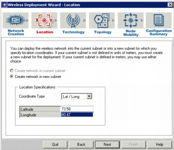
We will deploy a WLAN (Infrastructure) subnet in New York City first, using the latitude/longitude coordinates for the city in the Location screen of the wizard, as shown in the following figure.
Figure 29: Hotspot Access Provider Network–Subnet Location Specifications
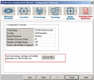
Accepting the defaults on the remaining screens, we save the specifications to a file by clicking the Save to File button, as shown in the following figure. For this example, we will reuse this file to deploy subsequent network segments.
Figure 30: Hotspot Access Provider Network–Save to File
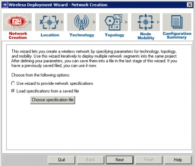
To deploy subsequent subnets and connect them to the backbone, we launch the wizard, and select “Load specifications from a saved file,” as shown in the following figure. We then select the previously saved file and continue to the Location screen to define the latitude/longitude for the next location.
Figure 31: Hotspot Access Provider Network–Use Saved File
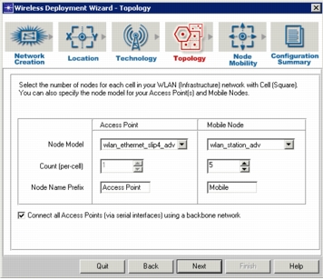
For each new subnet we deploy, we select the “Connect all Access Points (via serial interfaces) using a backbone network,” shown in the following figure. Since we selected this checkbox on the Topology screen during the creation of the first subnet, a backbone network already exists in the scenario. Each subsequent subnet created will be connected to this backbone.
Figure 32: Hotspot Access Provider Network–Connect Subnet to Backbone
We created three hotspot subnets: one each in New York City, Houston, and Phoenix. All three are connected via the backbone network. As shown in the following figure, you can drill-down into a subnet to see the topology for that subnet.
Figure 33: Hotspot Access Provider Network–Three Locations