Orbits
Satellite sites use an orbit to specify their location during a simulation. An orbit is the path around the earth along which the satellite site moves during simulation. If a subnetwork contains a satellite site with an assigned orbit, the parent subnetwork’s location and size do not affect the satellite’s orbital path. This is in contrast to fixed and mobile sites, whose positions are often defined relative to their parent subnetworks.
An orbit is defined by an orbit file, which holds data specifying the times and locations that the satellite site will pass through as the simulation progresses. You create orbit files using the Satellite Tool Kit program from Analytical Graphics, and then import the files. (See Satellite Tool Kit for more information on the Satellite Tool Kit.) The Satellite Tool Kit uses six orbital elements to compute the orbit at a set of discrete points evenly sampled in time. In addition, Riverbed Modeler users can create orbits via EMA (see “External Model Access” on page 1 in the Model File Access API Reference Manual).
When the position of a satellite site is required, the Simulation Kernel will recompute the location based on the points in the orbit. During simulation, the satellite site follows the orbit by traveling in a straight line from one position sample to the next, approximating the orbital path. Thus, the position of the site during simulation is determined for any time by linearly interpolating between the position sample just before that time and the next one after it in the orbit.
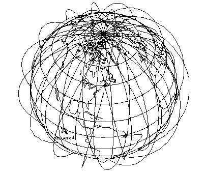
Figure 14: 3-Dimensional View of Example Polar Orbit
While satellite sites with orbits are useful for modeling satellites that move relative to the earth’s surface, some satellites’ motion can be modeled without an orbit. Because a geostationary satellite maintains a relatively fixed position over one point on the earth’s surface, a satellite site without a specified orbit can be an appropriate model. If the orbit attribute of a satellite site is set to NONE, then the initial values of the position attributes are used, as if the site were fixed to that location over the earth. This provides an increase in simulation efficiency, because the site’s position does not need to be recomputed each time that it is required. However, if the slight perturbations of a satellite’s position in geostationary orbit are important, then a geostationary orbit should be specified.
After you import an orbit file, you can view satellite motion using the op_vuorb program. This program also allows you to access the contents of the orbit file. For more information, refer to Chapter 4 “Viewing Satellite Orbits” on page 71.
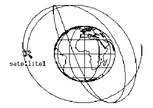
Figure 15: Satellite and Orbital Path in op_vuorb
Satellite Tool Kit
The Wireless functionality allows you to import orbits created with the Satellite Tool Kit Free version, from Analytical Graphics, Inc. STK Free can be obtained from the Analytical Graphics web site (http://www.stk.com).
Importing an STK Orbit
You can use either of two methods to import an STK orbit file. Both methods convert the .v or .sa file to an .orb file and store the file in your primary model directory. The second method also assigns the orbit to a satellite site.
Note: Only .v or .sa format orbit files created in STK 3.0 or higher can be converted.
Procedure 6: Importing and Storing an STK File
-
Open any project.
-
Choose Topology > Import STK Orbit.
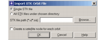
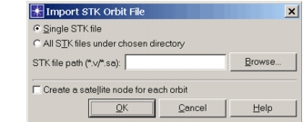
The Import STK orbit file dialog box appears.
-
Choose either Single STK file or All STK files under chosen directory.
-
Select the checkbox “Create a satellite node for each orbit” if you want to create individual satellite nodes in the topology.
These individual nodes are placed in the top subnet workspace for each imported orbit automatically. For each satellite node, its name is set to the corresponding imported orbit and it displays the imported orbit in top subnet.
-
Enter the full path name of the desired orbit file, or use the Browse button to display and select the file.
-
Click OK.
The file is converted and stored in the top directory listed in your mod_dirs preference.
Procedure 7: importing, Storing, and Assigning an STK File
-
Right-click on the satellite site to which you want to assign an orbit described by the STK file, and select Edit Attributes from the Object pop-up menu.
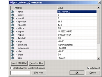
The site’s Attributes dialog box appears.
-
Select the Advanced checkbox.
Additional attributes and buttons appear.
-
Left-click the Import STK Orbit button.
The Import STK orbit file dialog box appears.
-
Choose either Single STK file or All STK files under chosen directory.
-
Select the checkbox “Create a satellite node for each orbit” if you want to create individual satellite nodes in the topology.
These individual nodes are placed in the top subnet workspace for each imported orbit automatically. For each satellite node, its name is set to the corresponding imported orbit and it displays the imported orbit in top subnet.
-
Click OK.
The file is converted, stored in the top directory listed in your mod_dirs preference, and assigned to the Orbit attribute of the selected site. In the workspace, broken lines show the orbit.