Default Link Closure Model (dra_closure)
This section describes the functionality and implementation of the default model occupying stage two of the Radio Transceiver Pipeline. This model is named dra_closure. The source code is provided in the file dra_closure.ps.c, which resides in the <reldir>/models/std/wireless directory.
Note: When you use dra_closure, you must also declare the external file closure_support.ex.c, as described in “Declare External Files” on page 49.
Invocation Context
The Radio Transceiver Pipeline determines the connectivity between a radio transmitter and a radio receiver by invoking the closure model immediately after completion of the transmission delay model. The simulation time at invocation is the start time for the packet transmission. The closure model allows dynamic enabling and disabling of radio links between radio transceivers. In other words, all pairs of transmitter channels and receiver channels that are evaluated positively by the receiver group model will be used in separate invocations of the closure model. This allows the pipeline to account for effects such as transmission range limitations, or dynamic changes to the attributes of the transmitters and receivers.
The result of the closure model invocation for each packet is a Boolean (OPC_TRUE or OPC_FALSE) value which represents the ability of the radio transmitter to reach the radio receiver of interest at the time of transmission. The Simulation Kernel expects this result to be placed in the packet’s OPC_TDA_RA_CLOSURE transmission data attribute. If the closure model returns a value of OPC_FALSE, indicating no connectivity between the transmitter and receiver, the Simulation Kernel will not execute the remainder of the pipeline stages for this particular packet transmission.
Terrain Modeling
The default link closure model includes support for terrain modeling using the “Terrain Modeling Module (TMM)” (TMM). With terrain modeling, closure is based on criteria set by the propagation model being used.
Closure Computation
When terrain modeling is not used, link closure is computed for all transmitted packets based on a ray-tracing line-of-sight model. The algorithm tests the line segment joining the transmitter and receiver for intersections with the earth’s surface (the earth is modeled as a sphere). If an intersection exists, the receiver cannot be reached and the remainder of the pipeline stages will not be executed for the packet of interest. This algorithm does not account for any wave-bending.
The ray-tracing line-of-sight algorithm uses the transmitter vector, receiver vector and difference vector (from the transmitter to the receiver) in performing calculations. These vectors are defined within a coordinate system whose origin is at the earth’s center. Vectors are denoted by ordered triples  , and can be represented as directed line segments beginning at an arbitrary point in space
 and ending at a point in space
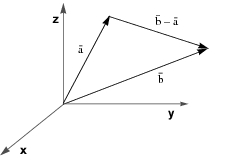
 . Vector addition can be performed by the pairwise addition of vector coordinates. The difference between two vectors
 is the vector that, when added to
 , results in
 . These relationships are depicted in Figure 101 for two vectors
 and
 represented at the origin.
Figure 101: Vector Subtraction Representation
The transmitter vector  , is the vector with initial point at the origin and terminating at the point
 , the location of the transmitter. Similarly, the receiver vector
 can be represented beginning at the origin and terminating at
 , the location of the receiver. The difference vector
 from the transmitter to the receiver originates at the point
 , and terminates at the point
 . Thus its coordinates are
 .
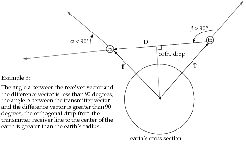
dra_closure uses a line-of-sight algorithm which tests the difference vector from the transmitter to the receiver for intersections with the earth’s surface. The model makes use of the fact that an intersection will not occur, and therefore line-of-sight will exist between the transmitter and receiver in any of the three following cases:
- the angle between the receiver vector
 and the difference vector
 has a magnitude greater than 90 degrees.
- the angle between the receiver vector
 , and difference vector
 , is less than or equal to 90 degrees and the angle between the transmitter vector
 and
 is less than 90 degrees.
- the angle between the receiver vector
 and difference vector
 is less than or equal to 90 degrees, the angle between the transmitter vector
 , and
 is greater than or equal to 90 degrees, and the shortest distance from the center of the earth to the line segment joining the transmitter and the receiver is greater than the radius of the earth.
Note: These three cases apply to calculations when a spherical earth model is used. For an ellipsoid earth, all calculations follow the case 3 approach.
Examples of each of these three cases are illustrated in Figure 102 and Figure 103. The locations of the transmitter and receiver are depicted by the encircled labels tx and rx, respectively.
Figure 102: Conditions for Link Closure - Case 1
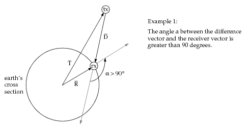
Figure 103: Conditions for Link Closure - Case 2
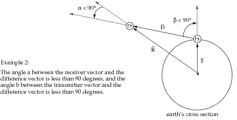
Figure 104: Conditions for Link Closure - Case 3
The Closure Model computes the dot product of  and
 to determine the size of the angle between the two vectors. The dot product can be given by
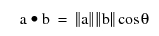
Therefore,
 when cos θ = 0 (i.e., when θ = 90 or 270 degrees)
 when cos θ > 0 (i.e., when θ < 90 or θ > 270 degrees)
 when cos θ < 0 (i.e., when 90 < θ < 270 degrees)