Default Received Power Model (dra_power)
This section describes the functionality and implementation of the default model occupying stage seven of the Radio Transceiver Pipeline. This model is named dra_power. The source code is provided in the file dra_power.ps.c, which resides in the <reldir>/models/std/wireless directory. An alternate version of this stage, for networks not using receiver channel state information, is in the file dra_power_no_rxstate.ps.c.
Invocation Context
The fundamental performance measure computed by the default Radio Transceiver Pipeline is the average power level of signals received by radio receiver channels. By computing this value for every relevant signal arriving at each radio receiver channel, the Received Power Model, which is the seventh stage of the pipeline, enables later stages to compute signal-to-noise ratio (SNR) and then derive bit error rate (BER).
The computation of received power occurs independently for each packet that is able to reach and affect the radio receiver channel (this determination is made by the Link Closure Model and the Channel Match Model, which occupy stages two and three of the pipeline). The Received Power Model is invoked by the Simulation Kernel to perform this computation immediately upon the completion of the Receiver Antenna Gain Model which occupies stage six of the pipeline. This invocation occurs at the simulation time where the leading edge of the packet arrives at the receiver channel. This time is given by the sum of the transmission start time and the propagation delay, and is provided in the packet’s OPC_TDA_RA_START_RX transmission data attribute.
The result of the Received Power Model invocation for each packet is a single double precision floating point value which represents the received power level for the packet. The Simulation Kernel expects this result to be placed in the packet’s OPC_TDA_RA_RCVD_POWER transmission data attribute.
Reception Exclusivity
In the default construction of the Radio Transceiver Pipeline, a signal lock value associated with the radio receiver channel object is used to prevent the simultaneous correct reception of multiple packets. While the pipeline could support the multiplexing of concurrent receptions onto a single outgoing packet stream of the radio receiver module, this is considered an uncommon case and is prevented by special logic incorporated into two stages of the pipeline. These are the Received Power Model and the Error Correction Model, which occupy stages seven and thirteen, respectively. The function of providing reception exclusivity at each radio receiver channel is not the primary objective of either of these stages, but has been incorporated within them for timing reasons.
The signal lock field of the receiver channel state information is used as a boolean to represent the busy or idle state of the receiver channel. The value OPC_TRUE is used to indicate that the channel is currently processing a valid packet which has the potential to eventually be received correctly. The value OPC_FALSE represents either a completely inactive channel with no incoming packets, or one at which all currently incoming packets do not have the potential to be received correctly. The determination of the potential for correct reception is initially made for each packet by the Channel Match Model which occupies stage three of the pipeline. Packets which might be received correctly are termed valid packets.
The Received Power Model dra_power is used to implement verification of the channel’s status, because it is invoked at the exact time of packet reception. Only valid packets which arrive at an idle receiver channel can cause the channel to become busy. For arriving invalid packets, the value of signal lock is not relevant; however, their power calculation is still performed because their noise contribution might affect the correct reception of other packets.
Valid and invalid packets are distinguished by testing the value of their OPC_TDA_RA_MATCH_STATUS transmission data attribute in the opening if statement. For valid packets, this attribute will have been assigned the symbolic constant OPC_TDA_RA_MATCH_VALID by the Channel Match Model that occupies stage three of the pipeline. The op_td_get_int() Kernel Procedure is used to obtain the object ID for the radio receiver channel at which the packet is arriving. This object ID is provided by the Simulation Kernel in the packet’s OPC_TDA_RA_RX_CH_OBJID transmission data attribute. This object ID is used to access the channel’s state information to check the signal lock value.
If signal lock is non-zero, indicating that the receiver channel is already busy acquiring a valid packet, the status of the newly arriving packet is overridden so that it is now considered as an invalid packet. This is done by using the op_td_set_int() Kernel Procedure to reassign its OPC_TDA_RA_MATCH_STATUS transmission data attribute to the symbolic constant OPC_TDA_RA_MATCH_NOISE, thus preventing the packet from later being correctly received and processed within the destination node.
If, on the other hand, signal lock is equal to 0 (OPC_FALSE), the channel is captured by the newly arriving packet, whose match status remains unchanged (the packet remains valid). The channel is then locked by assigning the signal lock attribute to OPC_TRUE.
Received Power Computation
For all arriving packets, whether valid or invalid, the average power level of the received signal is computed in the remainder of the dra_power() function. This computation is a link budget which takes into account the initial transmitted power, the path loss, and receiver and transmitter antenna gains.
The power (in units of watts) allocated to the transmission is obtained from the packet’s OPC_TDA_RA_TX_POWER transmission data attribute by using the op_ima_td_get_dbl() Kernel Procedure, and assigning the result to the automatic variable tx_power. The same Kernel Procedure is used to obtain the base frequency of transmission and the bandwidth of transmission from the transmission data attributes OPC_TDA_RA_TX_FREQ, and OPC_TDA_RA_TX_BW. These are assigned to the automatic variables tx_base_freq and tx_bandwidth, respectively. The values of these two variables are then used to compute the center frequency of the transmission which is held in the variable tx_center_freq. The wavelength lambda, of the packet transmission is given by the propagation velocity of light, C, divided by the center frequency, tx_center_freq.
The propagation distance (in meters) for the packet transmission is obtained from the packet’s OPC_TDA_RA_START_DIST transmission data attribute by using the op_ima_td_get_dbl() Kernel Procedure, and the result is assigned to the automatic variable prop_distance. If you are using terrain modeling, the value for propagation loss calculated by it is already set. Otherwise, the free space propagation loss is computed as a function of wavelength and propagation distance with the equation
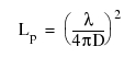
The result of this computation is placed in the automatic variable path_loss. In the case where the propagation distance is 0 (i.e., the transmitter and antenna are collocated), there is no loss and the path_loss variable is set to 1.
As a final stage of the computation of receiver carrier power, the transmitter and receiver antenna gains are extracted from the packet’s transmission data attributes OPC_TDA_RA_TX_GAIN and OPC_TDA_RA_RX_GAIN, respectively. The antenna gain values are obtained first in decibels (dB) and converted to non-logarithmic form so that they can be multiplied with the other variables of the link budget. The variable rcvd_power is then computed as the product of tx_power, tx_ant_gain, path_loss, and rx_ant_gain. This result is assigned to the packet’s OPC_TDA_RA_RCVD_POWER transmission data attribute for use by later pipeline stages and the Simulation Kernel.