Moving the Observer
When you view a simulation, you usually want to move the observer (eyepoint) to different locations to view the terrain and scene elements being simulated. In 3D Network Visualizer, you can move the observer using the keyboard and the mouse. There are two basic contexts in which you can move the observer:
- You can move it independently of any scene element. This is called absolute, or free-fly mode.
- You can attach the observer to an entity, in which case it moves with the entity. (You can also attach the observer to a prop. For details about attaching the observer to an entity or prop, please see Chapter 16 “Attaching the Observer” on page 243.)
Absolute mode and the various attachment types are collectively called attach modes.
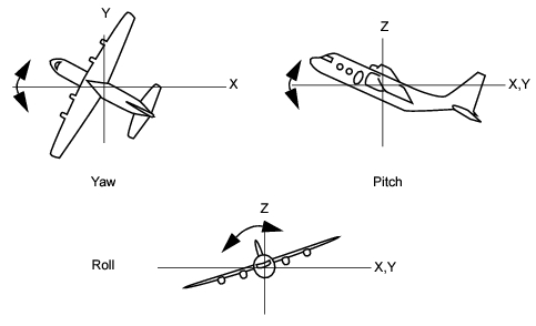
Regardless of which attach mode you are using, you can change the position and orientation of the observer. In the 3D Network Visualizer 3D projection, position is defined by X, Y, and Z coordinates that identify its location in the 3D world. Orientation describes the observer’s yaw (heading), pitch, and roll (Figure 35).
Figure 35: Orientation
Using the Compass to View the Observer’s Heading
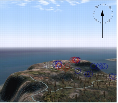
VR-Vantage can display a compass that always shows the heading of the observer. The compass is an observer mode setting. By default, it is enabled for Stealth and XR modes. In Figure 36, the observer’s heading is approximately Northwest.
Figure 36: Compass
Procedure 46: Enabling or Disabling the Compass
-
Choose Settings > Display.
The Display Settings dialog box opens.
-
Select the Observer Settings page (Figure 31).
-
Select the observer mode for which you want to change the compass setting.
-
In the list of observer settings, select or clear Compass.
Note: You can also enable or disable the compass by choosing Observer > Compass or clicking the Compass icon (
 ) on the Observer Settings Toolbar.
Editing the Compass’s Attributes
You can configure the compass by editing its schema (ChannelCompass) and model definition (smallCompass and largeCompass). (For details about editing schemas, please see “Creating and Editing Schemas“ on page 324.)
By default, all channels have the largeCompass keyword. To change the style of compass used for a channel, change the keyword in the Keywords attribute for the channel. To completely remove the compass, delete the keyword.
You can change the location of the compass by editing the location attribute. The permissible values are top, topRight, right, bottomRight, bottom, bottomLeft, left, and topLeft.
You can change the color of the compass by editing the darkTickColor and lightTickColor attributes. The color is defined using the OpenGL scheme for specifying RGBA. The first three values are the RGB color values. The fourth value specifies opacity. Each value can be from 0.0 through 1.0.