Viewing a Terrain Profile
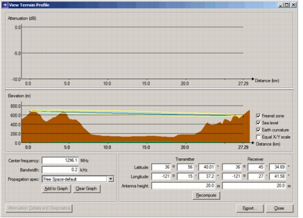
Terrain Modeling Module (TMM) helps you visualize the physics of a radio link by displaying a cross-section of the path between a transmitter and receiver (shown in Figure 13), as well as an optional plot of attenuation along that path. You can specify the antenna heights on each end, the operating frequency and bandwidth, and the propagation specification to use for these displays. You can also export data representing the terrain profile to a spreadsheet for further analysis.
Procedure 13: Viewing a Terrain Profile
-
Choose Topology > Terrain > View Terrain Profile.
-
Click on the location of the transmitter, then click on the location of the receiver.
The View Terrain Profile dialog box opens, showing the terrain profile for the specified path.
-
Customize the signal path to match your situation by changing any of the following parameters and clicking the Recompute button.
- Transmitter latitude, longitude, and antenna height
- Receiver latitude, longitude, and antenna height
- Center frequency (for Fresnel zone)
-
Control what is shown in the profile by selecting or deselecting any of the checkboxes to the right of the profile.
Note: Initially, the attenuation graph at the top of the dialog box is empty. For information about adding attenuation plots, see Viewing Attenuation Along a Path.
-
If desired, click the Export… button to send terrain profile data to a spreadsheet.
Figure 13: Terrain Profile