Creating a Propagation Specification
When you run a simulation that uses terrain data, the path loss calculations use a propagation model. Similarly, the calculations performed when displaying a signal strength plot also rely on a propagation model. When performing these operations, TMM needs to know both a propagation model name and the parameter values to use with it. This information is stored in a propagation specification. Each specification contains information about one or more propagation models and associated parameters. Propagation specifications are stored as an XML file with the file suffix .propag.xml.
A propagation specification defines one or more zones. Each zone is a geographic region associated with a specific combination of propagation model, parameter values, and frequency range.
If the specification contains several zones, TMM picks a zone with a compatible frequency range and containing the largest percentage of the signal path, then uses the propagation model specified by that zone. TMM uses this approach to pick a zone:
- Temporarily combine any zones that have the same propagation model and parameter set and treat them as a single zone in the following steps.
- Divide the signal path into 100 evenly spaced points (or whatever number is specified by the “Terrain Propagation Zone Resolution” preference).
- Determine what percentage of the points lie within each zone. Only zones containing at least one point will be considered in the remaining steps.
- Drop any zones whose percentage is less than that specified by the “Terrain Propagation Zone Ratio” preference.
- Drop any zones whose frequency range does not include the center frequency of the signal.
- From the remaining zones, choose the one with the highest percentage coverage of the signal path.
- In case of a tie, use the zone that is listed first in the propagation specification.
If no zones remain after this process, no propagation model is specified and any path loss calculation returns an error.
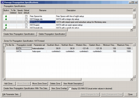
To create a propagation specification, choose Topology > Terrain > Manage Propagation Specifications… from the Modeler menu bar. This opens a dialog box that lets you create new propagation specifications and edit existing ones.
Note: For compatibility with legacy models, the built-in propagation specifications cannot be edited. To modify a built-in specification, select it and click the Create New Propagation Specification With This Data… button.
Figure 8: Manage Propagation Specifications Dialog Box
Procedure 5: Creating a Propagation Specification
-
Choose Topology > Terrain > Manage Propagation Specifications…
The Manage Propagation Specifications dialog box opens.
-
Click the Create New Propagation Specification… button, enter a name for the specification, and click OK.
-
Enter a description for this propagation specification.
-
If you want this propagation specification to be the default for simulations, select the Global Default checkbox next to the name of the specification.
-
Add a propagation model and parameter set:
Note: A new propagation specification has a default zone using the alphabetically first propagation model (usually CCIR) and no geographic or frequency limits. For the first zone, skip step 5.1 and just edit the default zone.
5.1 Click the Add Zone… button.
A new row is added to the Zones list.5.2 Click in the “Propagation model” field and select the model to use for this zone.
TMM includes several propagation models (such as Free Space, Longley-Rice, and Hata); optional models are available as well. You can create additional models of your own to meet special needs, as described in [Creating Your Own Propagation Model](tmm-13-op-80-21.md).5.3 Click in the “Parameter set” field and select a parameter set to use for this zone.
If you want to use a new parameter set, click the Edit Parameter Sets… button and follow the procedure described in [Editing Propagation Model Parameters](tmm-13-op-80-12.md). Your new parameter set will appear in the pop-up menu for you to select.5.4 If desired, specify geographic bounds and frequency limits for the zone. See Specifying Geographic Bounds for a Propagation Zone and Specifying Frequency Limits for a Propagation Zone for details.
5.5 Click the Apply Changes So Far button to save this zone.
-
If desired, repeat step 5 to add additional zones.
-
When you have defined all needed zones, click Apply Changes and Close.
Specifying Geographic Bounds for a Propagation Zone
The geographic area covered by a propagation zone is a rectangular region bounded by specified southern, northern, western, and eastern bounds. By default, these bounds are specified as <unlimited> and the zone encompasses the entire area of the network model.
Figure 9: Bounds in Manage Propagation Specifications Dialog Box

You can specify bounds for a zone to restrict it to a region appropriate to the propagation model and parameter set used, such as assigning a zone using the Hata model to a mostly urban area.
Procedure 6: Specifying Geographic Bounds for a Propagation Zone
-
Enter the desired bounds in the corresponding fields of the zone. For example, to set the northern border of the zone, enter a latitude value in the “Northern Bound (degrees)” field.
-
When you have entered all desired bounds, click one of the Apply Changes… buttons to save them.
Specifying Frequency Limits for a Propagation Zone
Frequency limits let you match a zone more closely to the propagation model and signal characteristics. A common use is to limit a zone to the frequency range for which the propagation model is valid. Another use is to define two zones with the same geographic area, but different propagation model/parameter set combinations and different frequency ranges. This allows the simulation to select a propagation model based on signal frequency.
Figure 10: Frequency Limits in Manage Propagation Specifications Dialog Box

To edit the frequency limits for a zone, use the following procedure.
Procedure 7: Specifying Frequency Limits for a Propagation Zone
-
Enter the desired frequency limits in the corresponding fields of the zone. For example, to set an upper frequency, enter a value in the “Maximum Frequency (MHz)” field.
-
When you have entered the desired frequency limits, click one of the Apply Changes… buttons to save them.
Available Propagation Models
For descriptions of the available propagation models, see