After the Import
Although you have imported a virtual model of your network, the live network continues to evolve. NetPlanner allows you to manage the network model along with the changes to your operational network.
- Viewing the Import Summary Report
- Incremental Imports and Updates to Network Model
- Using the Edge Connectivity Wizard
- Deleting Unconnected Nodes
- Viewing the Import Log
- Viewing and Editing Configuration Files After an Import
- Using the Virtual Command Line Interface
- Network Inventory Summary Report
Viewing the Import Summary Report
When the import is complete, a concise import summary appears. The report contains single-line descriptions and counts of significant events that occurred during the import.
Figure 19: Concise Import Summary Report
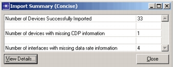
Hold the cursor over each item to display expanded information about the events.
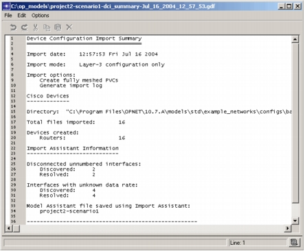
The View Details button, when clicked, opens a full import summary report.This report contains more information about the import including the timestamp, duration of process, specified import mode and options selected. It also shows the directory from which the device configuration files were imported and issues that were identified by the Import Assistant during the process.
Figure 20: Import Summary Report
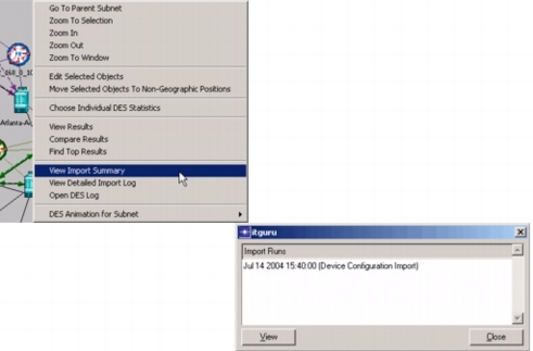
If you wish to review this import summary or other import summaries for previous imports, right-click in the workspace and choose View Import Summary. A dialog box opens that contains a list of import summary reports from previous device configuration imports. You can select any of the available reports for viewing.
Figure 21: View Import Summary
Incremental Imports and Updates to Network Model
Use DCI to update an existing network topology, whether that topology was created with DCI. You can
- add new devices to the network
- update the configuration files of some devices
- do a new import for the entire network
Figure 22: Subsequent Network Imports
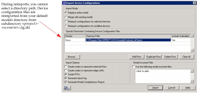
An import of a network model subsequent to an initial import is also called incremental import. There are several ways to perform an incremental import. Refer to Procedure 1 and note the following import modes related to incremental imports:
- Merge with Existing Model—Use this option to add devices to the existing topology. If some of the devices are already in the topology, these devices are replaced (that is, reimported) using the configuration files of this import. DCI matches the devices based on the hostname of the node.
- Reimport Configurations for Selected Devices—Use this option to update the configuration files of a few devices in the existing topology. The devices must already be selected in the workspace. If the devices you want to update are not currently selected, cancel this operation, select the devices, and start over.
- Reimport Configuration for Modified Devices—When you select this option, DCI will reimport configuration files for any devices that have been modified since the last import, based on comparison of the timestamp of the last import and the current time.
Note: No changes affecting network topology (i.e., addition/deletion of interfaces, IP address change, or change in interface status) as created during import from NetCollector are applied during incremental DCI.
The import mode, Reimport Configuration for Modified Devices, is the fastest method, especially for large networks. If the network is relatively small, or if you have many changes, consider replacing the entire model. All options use the basic import procedure described in Procedure 1. They differ only in the import mode used in the Import Device Configurations dialog box.
Table 6: Import Mode Usage for Updating Imported Topologies
| To… | Use This Import Mode… |
|---|---|
| Add new devices to an existing network | Merge with Existing Model |
| Update the configuration files of some nodes | Reimport Configurations for Selected Devices |
| Perform incremental import of changes in the network model | Reimport Configuration for Modified Devices |
| Reimport the files of all devices in the network | Replace Entire Model |
Using the Edge Connectivity Wizard
If you have disconnected nodes in your network model after the import, you might not have all the configuration information available to connect the nodes.
The Edge Connectivity Wizard lets you add IP connectivity to your network model and then save the configuration to a Model Assistant file to use during future import. Choose Topology > Open Edge Connectivity Wizard from the main window.
For more information, see "Edge Connectivity Wizard".
Deleting Unconnected Nodes
After an import, you may have some nodes that are not connected to any other nodes in the network model. You can remove these nodes quickly by selecting Topology > Delete Unconnected Nodes. A dialog box appears that lets you select individual unconnected nodes or all unconnected nodes to delete.
Viewing the Import Log
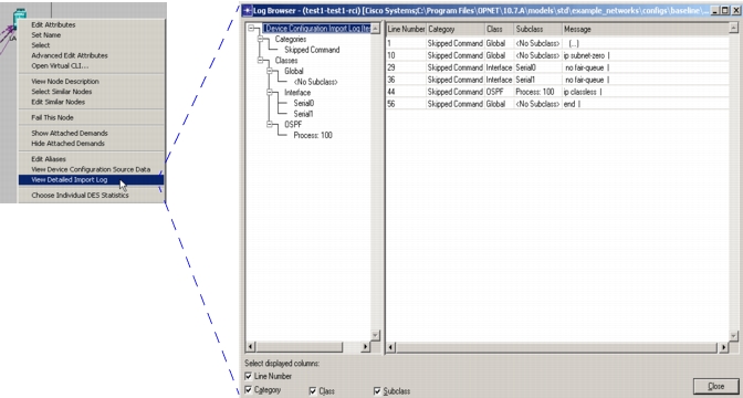
During the import, some commands in the device configuration files may have been skipped or ignored. You can see which commands were skipped during the import by selecting View Device Configuration Import Log from the Workspace pop-up menu. You can view the import log for an individual node by selecting View Device Configuration Import Log from the node’s Object pop-up menu.
Figure 23: DCI Import Log
Viewing and Editing Configuration Files After an Import
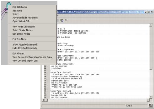
After an import, you can view the configuration file that DCI used to create a node in the Project Editor. To do this, select View Device Configuration Source Data from the node’s object pop-up menu.
Procedure 6: Editing a Configuration File of a Device
-
Right-click on the device in the Project Editor workspace and select View Device Configuration Source Data from the pop-up menu.
The configuration file appears in a text edit pad (see Figure 24).
-
Edit the configuration file.
Note: Do not remove the “!” (bang) between major sections of a Cisco configuration file. Doing so may cause subsequent imports to fail or behave abnormally.
-
Choose File > Save to save your changes.
-
Close the text edit pad.
After editing a configuration file in NetPlanner, you need to import the updated configuration file so that the changes you made are included in the topology. See Incremental Imports and Updates to Network Model for more information.
Figure 24: Viewing the Device Configuration File After Import
Using the Virtual Command Line Interface
The last section described how to permanently edit your configuration files through a text editor. If you want to edit the devices only for a particular project, you can use Virtual Command Line Interface (Virtual CLI), which allows you to edit Cisco routers and switches within the network model. The changes made with Virtual CLI are specific to the project within which you are working and do not affect the underlying source files.
The Virtual CLI has the same look and feel as the Cisco CLI, although it supports a sub-set of Cisco commands. Virtual CLI supports familiar Cisco CLI usage including shortcuts (such as typing ena instead of enable), command help access via “?”, and tab completion of a command.
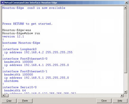
To access the Virtual CLI, right-click on a Cisco router or switch and select OpenVirtualCLI… The following figure shows an example of a Virtual CLI session.
Figure 25: Virtual Command Line Interface
Virtual CLI Preference
You can set the default source of the routing tables displayed in the virtual CLI by setting the Virtual CLI preference. To set the preference, navigate to Edit > Preferences and choose Virtual CLI in the treeview. Acceptable values for this preference are “Operational Network”, “Discrete Event Simulation”, or “Flow Analysis.” Quotation marks are required. The default value is “Flow Analysis.”
Viewing Routing Table
You can view the routing table by using either of the following commands:
show ip route—When you have routing tables from Flow Analysis, DES, or the operational network, and you have the Virtual CLI Preference set, NetPlanner determines the source of the routing table from the preference and displays the routes.show ip route source—You can override the value of the vcli preference by using the show ip route source source command, where acceptable values for source are DES, FlowAn, or Operational.
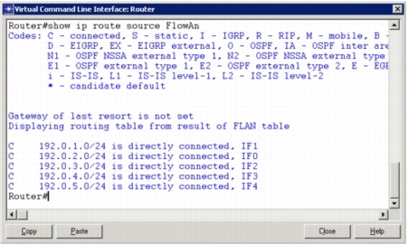
An example of the usage of this command is shown in the following figure.
Figure 26: Show Flow Analysis Routing Table
Updating the Routing Tables for Multiple Runs of a Simulation
If you run a simulation multiple times and want to check the routing tables again through VCLI, use the reload-data command. Because VCLI does not continuously check for updated routing tables, you must use this command to force VCLI to update the data and to display the new information.
Importing Configlets to Multiple Devices
You can import a subset of device configurations, called configlets, to Cisco and Juniper device configuration files. A configlet can contain anything that a complete device configuration file can contain, such as access lists, access list changes, “no” versions of commands, and modifications to routing protocols, for example. By using a configlet, you can enact a small change to your network model to determine how it will impact your operational network. If you want to apply a single configlet to a single device (one-to-one), see Importing a Configlet to a Device.
Note: When you edit or create configlets, you must include the “!” (bang) between sections of the configuration. See Preparing for the Import for an example.
WARNING: Do not make changes to the hostname or to the interface name in a configlet file. Doing so will result in the creation of a new device or interface without applying your intended changes to the original. Configlet contents are case-sensitive.
Figure 27: Apply Configlets Dialog Box
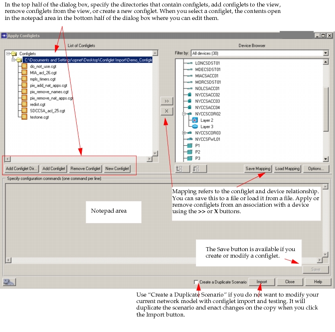
Through the use of the Apply Configlets dialog box, you can create and manage configlets, create and load mappings between configlets and devices, and import the configlets into your network model. The important elements of the Apply Configlets dialog box are listed in the following table.
Table 7: Elements of Apply Configlets Dialog Box
| Feature | Description |
|---|---|
| List of Configlets | Displays a view of directories you have added, which can be expanded to show files contained within. |
| Add Configlet Dir... | Opens a directory browser that lets you locate and select directories that contain configlets and that you want to view in the List of Configlets pane. |
| Add Configlet | Opens a file browser that lets you locate and select configlet files that you want to view in the List of Configlets pane. |
| Remove Configlet | Removes selected configlets from the view in the List of Configlets pane. This does not remove the configlet file from its storage directory. Likewise, if you select a directory and click Remove Configlet, you only remove it from the view. |
| New Configlet | Lets you name a new configlet, specify where it is stored, and edit it in the notepad area of the dialog box. |
| Device Browser | Displays a list of devices in the current network model that are supported for configlets. |
| Filter by | Lets you filter the view of devices by, for example, device type. The default is to view All devices. |
 |
Assigns a configlet file from the List of Configlets to a selected device in the Device Browser. |
 |
Removes a configlet file association from a selected device in the Device Browser. |
 |
- Up arrow moves the configlet to a prior position on the device to which it has been applied, in reference to the other configlets. Changes the order in which the configlet will be applied during import. - Down arrow moves the configlet to a later position on the device to which it has been applied, in reference to the other configlets. Changes the order in which the configlet will be applied during import. |
| Notepad/Display area | Displays the contents of a configlet. Provides a scratchpad for editing or creating configlets. If you select a configlet file in the Device Browser window, however, this area is Display only and does not allow you to edit the configlet. |
| Save Mapping | Saves the mapping you created between the configlet(s) and device(s) as a .gdf file that can then be shared with another user or used for later modeling. |
| Load Mapping | Loads a previously saved .gdf mapping file. |
| Options… | - Copy configlets—Saves a copy of the configlets in the same directory in which you have stored the device configuration files for the device. - Show Configlets Path—Specifies whether the full path or only the configlet file name is displayed in the Import Configlets dialog box. |
| Create as Duplicate Scenario | Creates a copy of the current scenario before importing the configlets, which preserves your original network model. |
| Import | Imports the configlets to the devices you specified. |
Procedure 7: General Workflow for Updating from Configlets
- Select Topology > Import Topology > Import from Configlets…
- Select a configlet from the List of Configlets pane in the Apply Configlets dialog box.
- Select one or more devices in the Device Browser pane.
- Add configlets to selected devices.
- Click the Import button to make the change to the configuration file and network model.
- Note the changes in the device attributes for modified devices.
Importing a Configlet to a Device
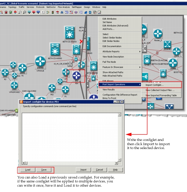
If you want to apply a single configlet to a single device, you can use the right-click Post-Import Operations menu choice “Import Configlet…”, shown in the following figure. This menu choice is available for Cisco and Juniper devices for which device configuration files have previously been imported. When you select “Import Configlet...”, a simple dialog box appears, as shown. In this dialog box, you can load a previously saved configlet file, create and save a new configlet file, and import the configlet to the device.
Figure 28: Importing a Configlet
Note: When you edit or create configlets, you must include the “!” (bang) between sections of the configuration. See Preparing for the Import for an example.
Note: When you use this option, you cannot select multiple configlet files and multiple devices to which to apply them.
Procedure 8: Import Configlet
-
Right-click on a node for which you have previously imported a device configuration file.
-
Select Post-Import Operations > Import Configlet…
-
Specify configlet.
3.1 Select the Load button, if you want to load a previously saved configlet file.
3.2 Enter text in the Notepad area, if you want to enter a new configlet. Select the Save button after you finish typing, if you want to save the configlet file for later use.
-
Select the Import button to apply the configlet to the selected device.
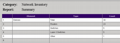
Network Inventory Summary Report
After an import, and on a periodic basis, you may want to see how many devices are in your network and of what type. If you have a rather small imported network model, it is a simple task to visually gather this information. For larger networks, however, it is a time-consuming, error-prone task to take inventory.
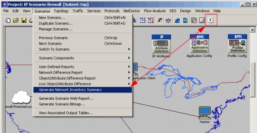
The Network Inventory Summary report is available at any time after an import. Running a Network Inventory Summary report after an incremental import allows you to keep your inventory files up-to-date. In the following figure, you can see that there are two ways to generate the report: through the drop-down menus or through the toolbar.
Figure 29: Generating a Network Inventory Summary
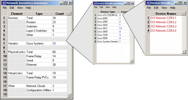
An example of a Network Inventory Summary report is shown in Figure 30. The summary includes
- Devices—A total count of devices, and a breakdown by device type
- Vendors—A count by vendor
- Physical Links—A total count of physical links, and a breakdown by type
- Virtual Links—A total count of virtual links, and a breakdown by type
- Other—A total count of other types of devices in the model, including network clouds, application models, configuration utilities, etc.
If a count listing is in blue text, there are further actions you can take. In the example shown in the following figure, certain counts are in blue text. To drill down even further, you can click on any number in blue. In the example below, we can go two levels deep to see the four Cisco WS-C2924M-XL switches listed.
Figure 30: Network Inventory Summary
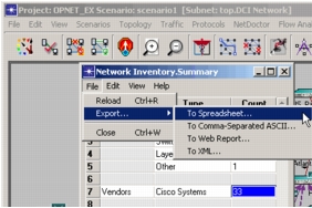
At any point in the summary, you can also export the report to any of the following file types:
- Spreadsheet (for example, MS-Excel)
- Comma-Separated ASCII
- Web Report
- XML
Figure 31: Export Network Inventory Summary
Exporting the report makes it easier to use the information for analysis, management reporting, and other requirements. The following figure shows an example of this Network Inventory Summary report exported to a web report format.
Figure 32: Export to a Web Report