Troubleshooting the Import
The initial network model is built from the imported device files. If adequate planning is not done before the import, the network model might not appear as expected. It is important to understand these issues prior to performing an import, so you may avoid surprises in the resulting topology. After the import, you may notice some of the following issues:
- Unable to Import—Import process fails
- Missing Devices—Expected devices not showing up in model
- Inferred Devices—Unexpected devices appear in model
- Inferred Layer-3 IP Clouds—Unexpected Layer-3 IP Clouds in model
- Differences in Connectivity—Physical connectivity is not as expected
- Network Clouds—Multiple subnets represented as one or more clouds
- Differences in Devices—Devices are not as expected
- Post-Import Caveats
Unable to Import
If after initiating the eXpress Data Import process there is a problem with the underlying parser process, the import process will stop and the network model will not be created.
There can be multiple reasons why this may occur:
- NetPlanner may be unable to start the parser process because a process is already running
- NetPlanner may be unable to connect to the parser process due to the port being in use or being blocked by firewall. You can solve this problem by changing the user preference "DCI Parser Port" to a port number that is not in use or by changing the firewall to allow the specified port.
- NetPlanner may timeout during the import process. You can solve this problem by changing the user preferences "DCI Parser Init Timeout" and "DCI Parser Status Timeout" to a higher number of seconds.
Missing Devices
You may notice that some expected devices are missing from the network model after an import. Missing devices can be caused by the following expected behavior:
- If a configuration file is not provided for a device, the device is not imported into the network model. Be sure to include all device configurations in the appropriate directory.
- If the
show versioncommand is not executed for a device, it may not appear in the network model. - If a VLAN interface is encountered during import, DCI will expect to have a corresponding switch configuration file. If none is found, DCI will skip the device with that interface with an error message. For more information on changing this behavior, see Importing Multi-Layer Switch Configurations.
- If you have a multi-layer switch with dual Multi-Service Feature Cards and did not include the output of
show module,show version, andshow redundancy, depending on your OS version, import may skip the device. See Table 2 for more information on required commands. - If you have a multi-layer switch but did not include the output of
show cdp neighbors detail, you may have two separate devices appearing in the network model (or neither, as mentioned in the previous bullet). If you choose not to re-import with the cdp information appended, you can create a model assistant file to couple the two devices, using Procedure 4. When you perform your next import, be sure to specify the model assistant file you created. The multi-layer switch will appear as one device.
Procedure 4: Create a Model Assistant File to Join Multi-Layer Switch
-
Select Topology > Model Assistant > Edit File…
The Edit Model Assistant dialog box opens.
-
Click on the Router/Switch Coupling tab.
Note: You may need to scroll to the right to see this tab. Use the directional arrow in the upper right corner.
-
Click in the Rows box, in the lower left corner, and increment the number by one to add a row.
-
Click on Specify... under Router Name, and enter the name of the Layer-3 device.
Note: This is the name of the RSM/MSFC/RSFC.
-
Click on Specify… under Switch Name, and enter the name of the Layer-2 device.
-
Save the Model Assistant file for use with future imports.
Inferred Devices
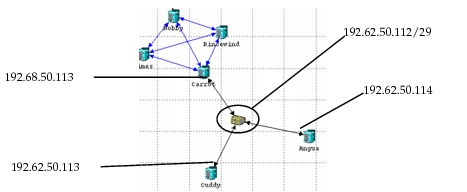
After an import, the network model may contain devices that you did not include in the configuration data. These inferred devices are created when two or more routers have interfaces to the same IP subnet. In this case, DCI uses a generic cloud model to connect the interfaces. The cloud model used to represent the IP subnet corresponds to the type of interfaces being connected and each cloud node is given the name of the IP subnet it represents.
In the following example network, DCI inferred and created an Ethernet switch between three router interfaces. This occurred because three configuration files specified interfaces that connect to the same IP subnet. All other interface data specified one-to-one connections, so DCI did not create additional switching devices.
Figure 18: IP Interface Connections in a Generated Topology
Inferred Layer-3 IP Clouds
After an import, the network model may contain Layer-3 IP clouds that were not in your configuration. These inferred IP clouds are created when there is no information about Layer-2 connectivity, but there is sufficient IP tunnel information to infer an IP connection between two interfaces. DCI uses an IP cloud model to connect the interfaces.
The IP clouds that appear in your network model after an import are created based on imported configuration files and the setting for the “Create Tunnel Clouds” preference. See Setting Device Import Preferences for more information.
Differences in Connectivity
DCI depends on certain information in the configuration files to make decisions about link names, connections, link types, and link speeds between end-points. The information in this section describes how the connectivity decisions are made.
- When importing router configuration data, DCI relies on the IP, Frame Relay or ATM information in your configuration files to configure router connections.
- By default, DCI names all interfaces based on the names found in the configuration files. If an inferred router model is used to represent the imported device and has extra interfaces, the interfaces are shutdown by default and have generic names in the format “IFn” (IF0, IF1, and so on).
- Interfaces that are part of an aggregate interface, such as EtherChannel, are connected based on the configuration of the aggregate interface.
- DCI colors each link according to its underlying technology (Ethernet, Frame Relay, ATM, etc.) and auto-assigns a name that indicates both interfaces to which it is connected.
- DCI treats all DPT/SRP interfaces as serial (PPP) interfaces.
- If the import process cannot determine an interface data rate from a configuration file, and you do not specify a data rate in the Import Assistant, DCI assigns default rates of T1 for serial interfaces and OC3 for ATM interfaces.
- Frame Relay and ATM interfaces that are connected through a homogeneous Layer-2 network are imported as Frame Relay and ATM interfaces. If these interfaces are connected through a Frame Relay-ATM Service Interworking (FRASI) switch, using a mixture of Frame Relay and ATM, the switch is modeled as an FRF.8 FRASI switch in the network. However, if these interfaces are connected through a heterogeneous Layer-2 network (containing Ethernet, as well as Frame Relay and ATM, within the same IP subnetwork), the interfaces are imported as serial interfaces to allow for connectivity.
- You can control whether DCI creates a serial cloud for mixed technologies by setting the preference Create Serial Clouds. See Setting Device Import Preferences for more information.
- For Frame Relay PVCs, the output from the show frame-relay map command will override PVCs configured in interface mode using the command frame-relay map ip.
- For ATM PVCs, the output from the show atm map command will override PVCs configured in interface mode using the command pvc along with the protocol command.
Network Clouds
The clouds that appear in your network model after an import are created based on imported configuration files and the setting for the device_import.collapse_clouds peference. To include this preference, you must enter it manually in the preference file using the following procedure.
Procedure 5: Add the device_import.collapse_clouds Preference
-
Edit the preference file and enter the following line in the appropriate device_import section:
device_import.collapse_clouds: “*value*”There are three possible values for this preference:
Don’t Collapse—This is the default value, which specifies that no clouds are collapsed during import. The result is that devices belonging to different subnets are imported as separate clouds. This may not be an accurate view of your network.
Collapse All—This option causes all imported clouds to be collapsed into a single cloud called “Network Cloud”.
Collapse per Protocol—This option causes clouds to be collapsed per protocol—ATM, Frame Relay, and serial—into either a cloud called “ATM Cloud” or a cloud called “Serial Cloud”, which comprises both Frame Relay and serial links.
-
Save the file and exit.
Changing the “device_import.collapse_clouds” preference alters the appearance of your network model after import.
Differences in Devices
DCI searches the model directories during the import for the device model that best matches each configuration file. If a matching device is not found, you may discover that the representative device does not suit your needs.
For example, the default device for a Cisco 12012 has 10 ATM ports, 8 Fast Ethernet ports, and so on. Suppose your specific router has no ATM ports but is loaded with Gigabit Ethernet and Fast Ethernet ports. Rather than showing too many ATM ports (in a shutdown status), it is better to define your unique devices in advance of the import.
Adding devices is described in Creating Device Models (Optional).
Missing VLANs
If a Cisco switch is configured as a VTP client, the configuration file may not contain all of the VLANs supported on the device. This results in an incomplete network model upon import. To avoid this problem, include the output of the “show vlan” command in the device configuration files, as listed in Table 2. The concise import summary report, shown in Figure 19, reports devices for which the “show vlan” output is missing.
Post-Import Caveats
If you plan to import traffic into the network model, there are some things to bear in mind with regard to expected DCI behaviors:
- DCI creates a list of aliases for each router that includes all IP addresses for which that router is responsible. With the exception of switches that have a Layer-3 card, no aliases are created for Layer-2 objects such as switches and clouds.
- By default, the import process does not create any traffic source or destination nodes (such as workstations or LANs). You can create LAN nodes at the edge of the network model by enabling the Create Edge LANs option in the Import Device Configurations dialog box. See Performing an Import with DCI for details. This option automatically creates Ethernet, Frame Relay, serial, ATM LANs, FDDI, or Token Ring.