Model Architecture
Node Architecture
Node models of some commonly used Wireless LAN objects are as follows:
Figure 676: Wireless Station and Workstation Nodes
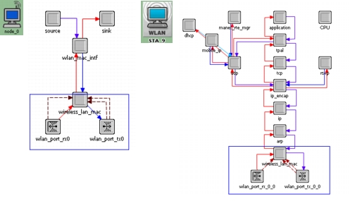
The Wireless LAN modeling of the MAC and the physical layer is comprised of the wireless_lan_mac process, transmitter, receiver, and the channel streams (as shown by the box in Figure 676). The ARP (address resolution protocol) is an interface between the MAC and the higher layers.
To study the WLAN MAC without a higher-layer stack (such as TCP/IP and applications), use the station node model that uses source and sink models to simulate higher layers. This node model can be used to do the following:
- Generate controlled traffic in the WLAN network and evaluate the performance of the MAC
- Simulate the effect of WLAN attributes independent of the higher layer
- Obtain shorter simulation time for large networks
This node model has the following station limitations:
- Bridges can be used to connect the BSSs of WLAN stations. A station can act as an access point, but it will function only as a relay within the BSS.
- You cannot observe the impact of the MAC on the higher layer
The higher layers are replaced by a bursty source and a sink process. There is a MAC interface that is equivalent to the ARP in the client/server model. The WLAN MAC process is independent of the higher layer as long as it has an appropriate interface.
Figure 677: Wireless Router
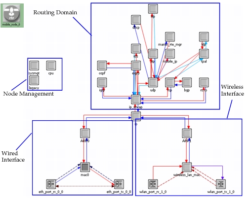
The WLAN router, shown in Figure 677, has one wireless interface and one ethernet interface. When it is configured as an access point, which is the default configuration, it can connect a BSS with a wireline distribution system. Do not configure a WLAN interface as an access point if it is part of a WLAN backbone network. When the wireless interface receives a data frame that does not belong to the same BSS, it will send the data frame to the higher layer for address resolution.