Migrating to IPv6
Tunneling mechanisms enable IPv6 sites to communicate with each other over an IPv4 backbone. The following types of IPv6 tunnels are supported:
- Manual tunnels (configured tunnels)
- Automatic tunnels
- Automatic 6to4 tunnels
- Tunnels over MPLS (6PE)
This section contains instructions for configuring each type of tunnel. Note that you cannot configure tunnels on host nodes, but you can use a multi-homed client/server to work around this limitation.
Manual IPv6 Tunnels
Manual tunnels are also referred to as configured tunnels. When configuring manual tunnels, note the following:
- The destination address of a manual tunnel must be explicitly specified.
- A separate tunnel is needed for each IPv6 site that the node communicates with.
- There is no limit on the number of manual tunnels you can configure on a router.
Even though you can configure unidirectional tunnels, practical considerations require a matching tunnel in the opposite direction. To configure a bidirectional tunnel, follow Procedure 66 for both end nodes.
Procedure 66: Configuring One End of a Bidirectional Tunnel
-
In the node’s Attributes dialog box, create a tunnel interface by adding a row to the IP > IP Routing Parameters > Tunnel Interfaces attribute. Give this tunnel interface a unique name by configuring the Name attribute.
-
Set the Routing Protocols attribute to “None.”
-
Click in the Tunnel Information attribute to open the Tunnel Information table.
-
Set the Tunnel Mode to “IPv6 (Manual).”
-
Specify the destination address of the tunnel under the Tunnel Destination attribute. The destination address must be an IPv4 address.
-
Set the Tunnel Source attribute to the name of a connected interface on the node.
-
Click OK to close the Tunnel Information and Tunnel Interfaces attribute dialog boxes (or collapse the Tunnel Information and Tunnel Interfaces attribute if you are navigating using the treeview in the main Attribute dialog box).
-
Add a row to the IP > IPv6 Parameters > Tunnel Interfaces attribute.
-
Set the Name attribute to the same value used in step 1.
-
Configure the link-local address and global addresses. At least one global address must be configured.
-
By default, RIPng will be enabled on the interface. Disable it if necessary.
-
Click OK in all open dialog boxes to save your changes.
End of Procedure 66
For correct tunnel operation, the tunnel’s destination address for one direction should correspond to the source interface of the tunnel in the other direction. For example, if a tunnel is configured between Nodes A and B, the destination address specified on Node A must correspond to the Source interface specified for the tunnel on Node B, and vice versa.
Automatic IPv6 Tunnels
Automatic tunnels can be used to tunnel packets whose destination address is an IPv4-compatible IPv6 address. The operation of automatic tunnels is described in RFC 2893 Sec 5. For automatic tunnels to work properly, the IPv4-compatible addresses configured on a node must have a subnet mask length of 128 bits.
You can use a single automatic tunnel on a router to tunnel packets to all destinations that have IPv4-compatible addresses. Because of this, the model does not support the configuration of multiple automatic tunnels on a node. Procedure 67 describes how to enable automatic tunneling on a router.
Procedure 67: Enabling Automatic Tunneling on a Router
-
In the node’s Attributes dialog box, create a tunnel interface by adding a row to the IP > IP Routing Parameters > Tunnel Interfaces attribute. Give this tunnel interface a unique name by configuring the Name attribute.
-
Set the Routing Protocols attribute to “None.”
-
Click on the Tunnel Information attribute to open the Tunnel Information table.
-
Set the Tunnel Mode to “IPv6 (Auto).”
-
Set the Tunnel Source attribute to the name of a connected interface on the node.
-
No additional configuration is needed for the IPv6 Parameters attribute.
-
Click OK in all open dialog boxes to save your changes.
End of Procedure 67
6to4 Tunnels
6to4 tunnels can be used to tunnel packets to destinations that use 6to4 addresses. 6to4 tunnels are described in RFC 3056. Modeling of 6to4 networks that have an ISP relay router, as described in RFC 3056 Sec 5.2.1, is supported. Procedure 68 describes how to automatically configure a 6to4 tunnel on a router (preferred method) and Procedure 69 describes how to manually configure the 6to4 tunnel.
In addition to configuring the 6to4 tunnel on the router, you must manually configure all IPv6 nodes behind the tunnel router with an address that starts with 2002 and embeds the public IPv4 address inside the IPv6 address.
Procedure 68: Automatically Configuring a 6to4 Tunnel on a Router
-
Select the routers in the project workspace between which you want to configure 6to4 tunnels.
-
Select Protocols > IPv6 > Create 6to4 Tunnels on Selected Nodes.
Result: The tunnel interfaces are automatically created and configured.
This utility creates a 6to4 tunnel under the attribute IP Routing Parameters > Tunnel Interfaces, assigns it an IPv6 address under the attribute IPv6 Parameters > Tunnel Interfaces, and creates a static route under the attribute IPv6 Parameters > Static Routing Table.
End of Procedure 68
Procedure 69: Manually Configuring a 6to4 Tunnel on a Router
-
In the node’s Attributes dialog box, create a tunnel interface by adding a row to the IP > IP Routing Parameters > Tunnel Interfaces attribute. Give this tunnel interface a unique name by configuring the Name attribute.
-
Set the Routing Protocols attribute to “None.”
-
Click in the Tunnel Information attribute to open the Tunnel Information table.
-
Set the Tunnel Mode to “IPv6 (6to4).”
-
Set the Tunnel Source attribute to the name of a connected interface on the node.
-
Add a row to the IP > IPv6 Parameters > Tunnel Interfaces attribute.
-
Set the Name attribute to the same value used in step 1.
-
Configure the link-local address and one global address. The global address of the interface must be a valid 6to4 address.
-
Add an IPv6 static route (IP > IPv6 Parameters > Static Routing Table) to the destination 2002::/16 with the next hop attribute set to the name of the 6to4 tunnel interface.
-
Click OK in all open dialog boxes to save your changes.
End of Procedure 69
Tunneling IPv6 over MPLS (6PE)
You can tunnel IPv6 traffic through an MPLS network using multi-protocol BGP. You must first configure multi-protocol BGP to carry the IPv6 prefix information and to redistribute IPv6 routes. Use the following procedure to configure 6PE.
Procedure 70: Configuring IPv6 Tunneling over MPLS
-
Open the Network Browser by choosing View > Show Network Browser.
-
(Optional) Select the PE routers you want to configure as IPv6 IBGP peers in the Network Browser.
This step is only necessary if you do not want to apply the changes to all routers in the network model.
-
Add IPv6 to IBGP peers currently using IPv4 by choosing Protocols > BGP > Configure IBGP Peers…
Result: The dialog box opens.
Figure 296: Configure IBGP Peers Dialog Box
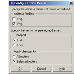
3.1 Select the checkbox for Address family IPv6.
3.2 Unselect the checkbox for Address family IPv4.
3.3 Select “Apply changes to” All routers or Selected routers. See optional step 2.
3.4 Click OK to apply and save your changes.
3.5 Click OK to close the summary dialog box.
-
Set the BGP start time.
Note: This is required because the LSPs are signaled by default at 150 seconds, and these LSPs must be up and running when BGP exchanges IPv6 routes so that the LSPs can be installed as the outgoing interfaces.
4.1 Choose Protocols > BGP > Configure Start Time…
4.2 Leave the distribution as constant, and set the start time as 160.
4.3 Select the radio button for “All Routers,” and then click OK.
-
Redistribute IGP into BGP, for example RIPng.
Note: By default, all IPv6 enabled interfaces run RIPng, so the routing protocol does not need to be explicitly configured.
5.1 Select your PE routers in the Network Browser, if you have not already done so. See step 1.
5.2 Choose Protocols > BGP > Configure IPv6 Route Redistribution.
5.3 In the routing protocol configuration dialog box, set the status of RIPng to Enabled.
5.4 Select the “Selected Routers” radio button, and click OK.
End of Procedure 70