HAIPE Attributes (Local)
All HAIPE and related protocol specific attributes are found under the "Security" category on the HAIPE and GDC Server device models.
Figure 156: HAIPE Model Device Attributes
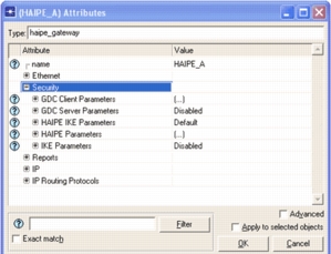
The following table lists a brief description of all the major parent attributes that pertain to the HAIPE model:
Table 70: HAIPE Attributes
| Attribute | Description |
|---|---|
| GDC Client Parameters | The Generic Discovery Client (GDC) attributes for the client portion of the protocol |
| GDC Server Parameters | The Generic Discovery Client (GDC) attributes for the server portion of the protocol |
| HAIPE Parameters | Used to configure all HAIPE-specific table structures and features. |
| IKE Parameters | Used to configure all Internet Key Exchange (IKE) related attributes. |
The following sections expand on how to configure each of the HAIPE major parent attributes. Not all child attributes will be discussed; instead only those that are commonly used or those that could significantly alter the behavior of the model will be presented.
GDC Client Parameters
The majority of the attributes required to configure the client portion of the GDC protocol are actually found within the HAIPE Parameters compound attribute. The GDC Client Parameters allow the user to Enable/Disable the protocol and to establish a time for when the protocol "starts". If the protocol is disabled then even if the HAIPE is properly configured for discovery, the GDC protocol will not be able to operate.
When GDC "starts", it will create a single Registration message containing the current contents of the LEPT and will then send that to the GDC servers configured in the RTAT. Setting the start time to be later in simulation (by default it is configured to start sometime between 75 and 80 seconds into simulation) allows the PT routing protocols (i.e. RIP) and the LEPT to converge and thus reducing the number of GDC Registration messages sent by the HAIPE in order to reach steady state.
GDC Server Parameters
The GDC Server Parameters lets you configure the server portion of the GDC protocol. This compound attribute is available on HAIPE devices as well as on the GDC standalone server node since both support that portion of the protocol. This attribute is used to Enable/Disable the server side of the protocol as well as define its behavior.
The Server Port attribute specifies the server-side UDP port that will be opened to listen for all GDC messages. The value specified here should match the destination port specified on any GDC-clients that use this server.
The Multicast Addresses attribute lets you specify a set of multicast groups that the server can join—and from which the server receives Registration and Solicitation messages. These multicast groups should match the destination addresses specified on any GDC-clients that will use multicast to reach this server. When configured on a standalone GDC server, this attribute triggers the IGMP protocol to transmit an unsolicited Membership Report (Join) message to the PT enclave.
All timers associated with the protocol are specified here as well. Of particular importance is the Prefix Lifetime Multiple attribute, which defines how the server times out prefixes from its database. It specifies the multiple of an advertised prefix lifetime in received registration messages to use as the timeout interval for a particular prefix. After this multiple of the prefix lifetime has elapsed, the server should delete the associated prefix and no longer respond to Solicitation Queries based on this expired information.
As an example, consider a Registration message received by a GDC Server with a prefix lifetime of 100 seconds. Normally, this means that the HAIPE advertising that prefix will continue to send Registration messages containing that prefix every 100 seconds. If the GDC Server has configured a Prefix Lifetime Multiple of 1.0, then 100 seconds after that Registration message is first received it will time it out of its database unless a new Registration message for that same prefix from that same HAIPE is received; at which point it will start the timer again. This obviously doesn't give much room for error in the transmission of Registration since if just one of those Registration messages is dropped the server will time the entry out of its database. A safer configuration might be to use a Prefix Lifetime Multiple of 1.5, which would require the GDC Server wait 150 seconds in this case before it times the prefix out of its database. This provides more room for packet drops.
Note: The HAIPE IS does not specify any requirements for how the GDC Server should behave; only how responses to GDC Client messages sent by HAIPEs should be formatted. The model uses a default Prefix Lifetime Multiple of 3.0 but there is no guidance available as to how this value should be configured.
HAIPE Parameters
The HAIPE Parameters contain the meat of the attributes required to configure a HAIPE device model. All of the table structures defined previously are configured here as well as all behavioral aspects and supporting protocols (i.e. IGMP, RIP, Discovery, IKE) that the HAIPE may be using. However, before getting into those more complicated configuration, the most important attribute within the model will be discussed first: Version. This attribute allows the user to specify which version of the HAIPE IS the model should be based on. The version of the HAIPE IS, in turn, dictates which features are available. The model will only allow configuration of features that are available in the configured version of the HAIPE IS. For example, choosing version 1.3.5 would disable features that were not introduced until a later HAIPE IS version such as IGMP Host Mode or RIP Speaker.
This section will be further broken down and categorized by table structure and/or supporting protocol to provide more in depth detail as to what is required to configure for each of them. Additionally, each of the categories will be presented in the order in which they should be configured (due to potential dependencies).
Key Configurations
The Key Configurations attribute is where all information related to key material that is "loaded" onto the HAIPE device is configured. While the key information configured here is not used to encrypt/decrypt packets (the model does not support this) it is used to link multiple table structures together (i.e. the CT SPD to the SAD or the CT SPD to the FFSA Table).
Note: The HAIPE model does NOT do any actual encryption/decryption of packets. These operations are simulated by accounting for the time to complete them as well as accounting for the overhead they impose on each packet.
Child attributes within the Key Configurations are used to store information related to pre-placed key chains (PPK Chain), as well as Firefly keys that are used for IKE negotiation. The following table provides a description of these child attributes and the cases in which they must be configured.
Table 71: Key Configurations Sub-Attributes
| Attribute | When Required | Description |
|---|---|---|
| PPK Chain Table | When manual security associations are used | Each entry in this table represents a single PPK Chain and is referenced by its PPK Chain ID attribute. The PPK Chains configured in this table are then mapped to outbound Protect-PPK security policies in the CT SPD and to manual security associations configured in the SAD. A lookup into the SAD for traffic that matches a Protect-PPK security policy is done using a tuple of (Outbound CT SPD ID, Peer CT Address, PPK Chain ID). The outbound CT SPD ID and PPK Chain ID come from the Protect-PPK security policy that was matched to the packet; the Peer CT Address comes from the result of the PEPT lookup. |
| FF Key Table | When dynamic security associations will be negotiated using the IKE protocol | Each entry in this table represents a single Firefly key and is referenced by its FF Key ID attribute. The Firefly keys configured in this table are then mapped to outbound Protect-FF security policies in the CT SPD (when the configured HAIPE version is 1.3.5) or to FFSA Table entries (when the configured HAIPE version is 3.0 or higher). The variable mapping is due to the fact that the FFSA Table structure was introduced with the HAIPE MIB which is part of HAIPE IS 3.0. The FF Key ID is then used as part of the IKE exchange. |
You can also populate the PPK Chain Table by using the "Protocols > IP > HAIPE > Configure PPK Chain on Selected HAIPEs…" utility. Additionally, the FF Key Table can be populated by using the "Protocols > IP > HAIPE > Configure Firefly Key on Selected HAIPEs…"
Note: PPK Chains and FF Keys can be used within multiple linked tables (i.e. Manual SAD, FFSA Table and CT SPD). Additionally, you are not required to configure a separate PPK Chain or FF Key for each linked table entry that requires them. As an example, a HAIPE box may have a single Firefly key that is used for all dynamically negotiated security associations.
Transform Configurations
The Transform Configurations attribute is where all of the cohesive sets of HAIPE cryptographic properties (referred to as a transform) are configured. Each transform defined within this table can then be used by security associations (manual and dynamic) to encrypt and decrypt the packets that use them. From a modeling perspective, the transform determines the packet format and what the imposed overhead on the packet will be (as stated previously, the model does not perform any actual encryption/decryption of the packets). Additionally, unique delay values (for encryption and decryption separately) can be assigned to each transform so that the processing overhead associated with using a particular set of cryptographic properties can also be modeled.
Transforms are mapped to manual security associations and FFSA Table entries via the configured Transform ID/Suite Name attribute. IKE will use the transforms specified in the FFSA Table and assign one of them to dynamically negotiated security associations (the IKE protocol makes the decision as to which one to use). Each security association must have a transform associated with it that is common on both sides of a security association. While the Transform IDs do not need to match up (these are locally significant only) the configured cryptographic properties do need to match.
NOTE: Transforms may be configured locally on a HAIPE device using the Transform Configurations attribute (in which case they are only available to the local HAIPE device) or may be configured globally using the haipe_transform_config utility object (in which case they are available to all HAIPE devices in the network). Globally defined transforms will have the "GLOBAL" suffix added to the configured Transform ID/Suite Name when mapping them to manual security associations and FFSA Table entries.
You can also populate the Transform Configurations by using the "Protocols > IP > HAIPE > Configure Transform on Selected HAIPEs…" utility.
The following table provides a description of the attributes that make up a transform and the cases in which they must be configured.
Table 72: Transform Attributes
| Attribute(s) | When Required | Description |
|---|---|---|
| Encryption Algorithm, Integrity Algorithm, Crypto Block Size, ESP Mechanism/Mode | For every transform that is defined | These attributes compose the cryptographic properties that define a single transform. The configuration of these attributes will define how a packet gets encrypted. The transforms configured for the two security associations that make up a one way connection (one outbound and one inbound) must have matching configurations of these attributes in order for communication to be possible. |
IKE
HAIPE is capable of dynamically negotiating security associations using the Internet Key Exchange (IKE) protocol. From a HAIPE configuration perspective, there are a number of things that must be done in order to enable the use of IKE. How IKE is configured really depends on which version of the HAIPE IS the device is configured with. There are major differences in the way IKE is configured when the version is 1.3.5 versus when the version is 3.0 or higher. IKEv2 is available when the version is set to 4.1. The following table should serve as a guide when configuring IKE on a HAIPE device.
Table 73: IKE Configuration Guide
| HAIPE Version | Required Configurations | Behavior Description |
|---|---|---|
| 1.3.5 | IKE Configuration | When the version is 1.3.5, the IKE Configuration attribute acts as a toggle; it can be enabled or disabled. Simply setting this attribute to Enabled will allow HAIPE to dynamically negotiate security associations. |
| 3.0 or higher | IKE Version, FFSA Table, CT Outbound SPD, CT Inbound SPD | When the version is 3.0 or higher, the IKE Configuration attribute is a compound attribute and has two children: IKE Version and FFSA Table. IKEv2 is available when the version is set to 4.1. The FFSA Table will be discussed more, later in this section. The CT SPD must be configured to allow the IKE messages in the outbound and inbound directions. This will also be discussed in more detail later in this section. |
This section discusses how to configure HAIPE to use IKE, but you may still need to configure the IKE protocol itself. That is done via the IKE Parameters and HAIPE IKE Parameters attributes (described in other sections).
IKE is initiated when traffic is matched to a Protect-FF outbound CT security policy and the SAD lookup fails. When the configured HAIPE IS version is 1.3.5, this policy also specifies a Firefly key that gets provided to IKE when the command to initiate an exchange is sent. Additionally, all transforms specified in the transform table (Transform Configurations) are provided to IKE to then be offered up when initiating an IKE exchange. Therefore, the order of transforms in the table is important because it becomes an ordered list. The first transform supported by the responder is the one used for the negotiated security association.
When the configured HAIPE IS version is 3.0 or higher, the configuration of IKE is a bit more complicated because of the presence of the FFSA Table. IKE is initiated in the same way for 3.0 and higher as it is for 1.3.5, however instead of a Firefly key, the Protect-FF outbound CT security policy specifies an FFSA Table entry to use (mapping to an FFSA Table entry is done via the FFSA Table's FFSA Entry ID attribute). This configuration provides additional user control over the configuration of dynamic security associations by allowing the configuration of cryptographic and network properties that were not previously possible. The following table provides a description of the attributes that make up an FFSA Table entry.
Table 74: FFSA Table Attributes
| Attribute(s) | Description |
|---|---|
| FF Key ID | Specifies the Firefly key to use when a dynamic security association is created using this FFSA table entry. The FF Key ID links into the Firefly Key Table (described in the Key Configurations section). |
| Transform IDs/Suite Names | Specifies the transforms that can be offered up to the peer HAIPE when an IKE session is initiated using this FFSA table entry. This is an ordered list so the first transform in the list will be preferred. This can be configured as "Any" which allows all transforms present in the Transform Configurations table to be offered up during the IKE exchange. Just as when the HAIPE version is configured as 1.3.5, that table becomes an ordered list so the order of its configuration becomes important. |
| Outbound CT Security Policies, Inbound CT Security Policies | These attributes do not correspond to anything in the HAIPE MIB or the HAIPE IS but have been added to the model as a way of allowing for the negotiation of multiple security associations to the same peer. The configuration of these attributes is optional. At the time this document was written, there were no HAIPE vendors that supported negotiating multiple IKE SAs to the same peer. These attributes specify lists of outbound and inbound CT security policies that get linked to the two security associations (outbound and inbound respectively) created as a result of an IKE exchange that uses this FFSA Table entry. If the value of Any is used (which is the default), then any security policy can link to this security association. |
| DSCP Bypass, ECN Bypass, DF Bypass, Transmit PDUN Messages, PHRD Configuration, TFS Configuration | These attributes all specify networking and traffic protection attributes that will be applied to any IKE security association created as a result of using this FFSA Table entry. Prior to the FFSA Table (i.e. version 1.3.5), any SA dynamically created would have these attributes set to their default values automatically by IKE. With the FFSA Table, these attributes (that are configurable for manual SAs) are now configurable for dynamic SAs. The configuration of these attributes is optional as they are already configured with default values. |
| Supported Security Classifications | Specifies set of security levels that are supported by an FFSA entry. During an IKE exchange, the resulting SAs will inherit the highest security classification from the intersection of the local and remote "supported security classifications" sets. If no common security level exists, the IKE exchange will fail. |
| RoHC Configuration | These attributes specify the configuration of Robust Header Compression (RoHC) for the SAs dynamically created from this FFSA entry. They are described in more detail under the RoHC attributes section. |
| Maximum Receive Bandwidth | For IKEv2 only. Specifies the maximum bandwidth that the HAIPE will receive on SAs dynamically created from this FFSA entry; this value will be negotiated via the IKE exchange. The default value is Unlimited. |
When the HAIPE version is configured as 3.0 or higher, there is one final configuration required to enable the use of IKE: the CT SPD. A Bypass policy must be configured in the outbound direction and a Protect-FF policy in the inbound direction in order to allow the IKE control traffic that is sent/received in the clear (i.e. messages 1-4) to be appropriately processed. The best way to do this is to create policies that match on UDP Port 500 (which is the standard port that IKE uses) as shown in the following figure.
Note: The CT SPD table is found on the Security > HAIPE Parameters > Interface Information attribute.
Figure 157: Configuring CT Security Policy for IKE
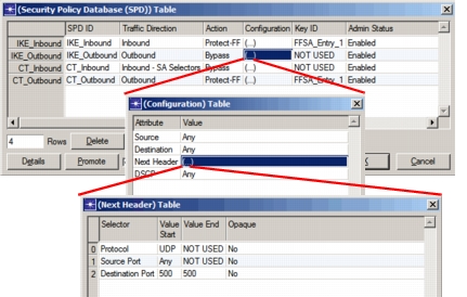
The Protect-FF policy is required for the inbound IKE traffic so that the IKE responder can identify a FFSA Table entry to use. The initiator has an FFSA Table entry to use because the outbound CT security policy configured with Protect-FF (that was matched to the packet) had the FFSA entry mapped to it. The responder does not have this luxury, so it must rely on the IKE message 1 that it receives and the inbound CT SPD to provide it this information.
Note: Configuring the SPD (both the PT and CT) will be discussed in more detail in the section on HAIPE Interfaces.
Local Enclave Discovery
Local Enclave Discovery and their related data structures are only available when the configured HAIPE version is 3.0 or greater.
Local Enclave Discovery specifically refers to the HAIPE's ability to learn information about the PT enclave that it is protecting. This can be done through manual configuration or via more dynamic means (i.e. RIP). The HAIPE model allows for the configuration of both mechanisms using two attributes: Manual Local Enclave Prefix Table (LEPT) and RIP/RIPng Configuration. The following table provides a description of each of these attributes and notes when the attribute needs to be configured.
Table 75: Local Enclave Reachability Attributes
| Attribute | When Required | Description |
|---|---|---|
| RIP/RIPng Configuration | When the HAIPE wants to discover local prefix information dynamically | Configures the RIP protocol's mode of operation within the HAIPE context. Passive mode allows for the discovery of PT prefixes while the HAIPE operates in RIP Silent Mode (no RIP messages sent). This mode is available in HAIPE IS version 3.0 and later. Active mode allows for the same functionality as Passive mode but also allows for remote prefixes present in the PEPT to be advertised to the HAIPE's local enclave. This mode is available in HAIPE IS version 3.1 and later. If dynamic discovery of the local enclave is not desired, then this attribute should be set to Disabled. Dynamically learned entries can be removed during the course of simulation based on the behavior of the RIP routing protocol. |
| Manual Local Enclave Prefix Table (LEPT) | When the HAIPE needs to be configured with information about its local PT enclave that can't be discovered dynamically | The Manual LEPT attribute allows for the user to manually add information about the prefixes the HAIPE is fronting. These entries will never be removed from the LEPT during the simulation. |
The only local prefix discovery protocol specified in the HAIPE IS is RIPv2 (for IPv4) and RIPng (for IPv6).
When configuring the RIP protocol, be aware of all of the available RIP routing protocol features, global attributes, and node attributes (configurable via the RIP Parameters compound attribute). In particular, be aware of the global Simulation Efficiency attribute for RIP or RIPng. If you are doing simulations with mobility or failure/recovery then you will want to make sure these attributes are configured as Disabled (they are Enabled by default). The following table describes the available RIP features called out in the HAIPE IS and which attributes are required to be set in order to properly configure those features.
Table 76: RIP Features on a HAIPE
| Feature | Attribute(s) Required | Description |
|---|---|---|
| Passive Mode | RIP/RIPng Configuration PT Inbound SPD IP Routing/IPv6 Parameters > Interface Information > Routing Protocol(s) RIP/RIPng Parameters > Interface Information > Silent Mode |
When HAIPE is configured in Passive Mode, it is only capable of learning about prefixes provided via the RIP routing protocol. Think of this as redistributing information from the RIP routing table into the LEPT. In order for this feature to be properly configured, the RIP (or RIPng) Configuration attribute must be set as Passive, the IP PT interface must be configured to use RIP (or RIPng) as a routing protocol, and the RIP (or RIPng) PT interface must be configured with Silent Mode Enabled. |
| Active Mode | RIP/RIPng Configuration PT Inbound SPD PT Outbound SPD IP Routing/IPv6 Parameters > Interface Information > Routing Protocol(s) RIP/RIPng Parameters > Interface Information > Silent Mode |
When HAIPE is configured in Active Mode, it is not only capable of learning about prefixes provided via the RIP routing protocol (as in Passive Mode) but is also capable of advertising remote prefixes present in the PEPT (with a corresponding reachable SA) via RIP (or RIPng). Think of this as redistributing information from the PEPT into the RIP routing table. In order for this feature to be properly configured, the RIP (or RIPng) Configuration attribute must be set as Active, the IP PT interface must be configured to use RIP as a routing protocol, and the RIP (or RIPng) PT interface must be configured with Silent Mode Disabled. |
| Default Route Advertisement | RIP Parameters > Process Parameters > IPv4-Any > Process Parameters > Default Information Originate | However you plan the PT routing architecture when HAIPEs are present, multiple routing domains will be created (at least initially) because the HAIPE causes the network to be broken up. Even when Active RIP is configured, it is not guaranteed that every potential remote PT destination will be advertised by the HAIPE via RIP (since Active RIP is only a reflection of what is in the HAIPE's PEPT). Due to this fact, there must be a default route propagated to or manually configured on all PT routers. Through the Default Route Advertisement feature, the HAIPE can be the source of its own default route by advertising it via RIP. This is only available when Active RIP is configured. |
There is one final configuration required to enable RIP: the PT SPD. A Bypass policy must be configured in the inbound and outbound directions to allow the RIP control traffic that is sent/received in to be appropriately processed. The best way to do this is to either create policies that match on UDP Port 520 (which is the standard port that RIPv2 uses), UDP Port 521 (which is the standard port for RIPng), or on the IP network address of all PT routers that would be exchanging RIP messages with the HAIPE device. An inbound PT SPD policy is required when the RIP (or RIPng) Configuration is set as either Passive or Active (since it will be receiving RIP messages in both cases). An outbound PT SPD policy is only required when the RIP (or RIPng) Configuration is set as Active (since that is the only configuration where RIP messages are actually sent by the HAIPE).
You can also use the Protocols menu to configure dynamic local enclave discovery: Protocols > IP > HAIPE > Configure RIP on Selected HAIPEs.
Remote Enclave Discovery
Remote Enclave Discovery specifically refers to the HAIPE's ability to learn information about remote PT enclaves protected by peer HAIPE devices. This can be done through manual configuration or via more dynamic means (i.e. Dynamic Discovery). The HAIPE model allows for the configuration of both mechanisms using two attributes: Manual Peer Enclave Prefix Table (PEPT) and Dynamic Discovery Configuration. The following table provides a description of each of these attributes and notes when the attribute needs to be configured.
Table 77: Remote Enclave Reachability Attributes
| Attribute | When Required | Description |
|---|---|---|
| Dynamic Discovery Configuration | When the HAIPE wants to discover remote prefix information dynamically | Configures all behavioral aspects of the dynamic discovery mechanism for the HAIPE. The attributes within the Dynamic Discovery Configuration apply to all discovery protocols (i.e. GDC). |
| Manual Peer Enclave Prefix Table (PEPT) | When the HAIPE wants to provide information about remote PT enclaves that can't be discovered dynamically | The Manual PEPT attribute allows for the user to manually add information about the prefixes that HAIPE peers are fronting. These entries will never be removed from the PEPT during the simulation. |
You can also populate the manual PEPT by using the "Protocols > IP > HAIPE > Import > Peer Prefix Information" utility. Several example manual PEPT import files are included with the HAIPE example project. These files are located in the <reldir>/models/std/example_networks directory and are named: HAIPE-<Scenario Name>_Peer_Prefix_Import.csv. The format is shown below.
Table 78: HAIPE Manual PEPT Import Format
| Column Number | Attribute | Potential Values |
|---|---|---|
| 1 | HAIPE that PEPT is being imported for | <Node Hierarchical Name> |
| 2 | PT Network Address | <IP Network Address> |
| 3 | PT Network Subnet Mask | <Subnet Mask> |
| 4 | Peer HAIPE Information | <Node Hierarchical Name><CT IP Address> |
| 5 | Administrative Cost | <integer value> |
The following section discusses how to configure HAIPE to use Dynamic Discovery, but you may still need to configure the individual discovery protocols themselves. That is done via the corresponding protocol attributes (i.e. GDC Client Parameters) which are described in other sections.
Dynamic Discovery is used when traffic is matched to either a Protect-FF or a Protect-PPK outbound CT security policy and the PEPT lookup that follows that outbound CT SPD check fails. Configuring the HAIPE to use dynamic discovery requires configuring a number of the table structures that are specific to discovery (that is, STAT, RTAT, and SRAT) that were described earlier in this document. The following table provides a description of the child attributes within the Dynamic Discovery Configuration attribute and discusses when they are needed.
Table 79: Dynamic Discovery Configuration Attributes
| Attribute(s) | Description |
|---|---|
| Status | Specifies whether the dynamic discovery of remote prefix information is enabled on this device. If set to Disabled, then no dynamic discovery protocol is used. |
| Registration Message Timers Solicitation Message Timers |
The Registration and Solicitation message timers are located within the Timers compound attribute. These attributes are used to modify the behavior of dynamic discovery protocols when sending registration messages (used for GDC only) and solicitation messages (used for all discovery protocols). The configuration of all of these attributes is optional, but there is one within the Registration Message Timers that is of particular importance: Prefix Lifetime. The configuration of this attribute dictates the lifetime advertised by this HAIPE in all GDC Registration messages it sends. This in turn dictates how often Registration keepalive messages must be sent to keep the GDC server(s) from timing out the information from its database. Additionally, it dictates the length of time that remote HAIPEs can allow that same information (dynamically discovered via the GDC server) to remain valid within its PEPT. The default configuration of this attribute is Infinite, which means that the information will never time out and periodic keepalive Registration messages are never sent. |
| Registration Transmission Address Table (RTAT) | Configures the RTAT which is a required configuration when the GDC discovery protocol is being used. More information about this table structure is provided in an earlier section. Registration messages are sent to all servers in this list (at the same time) until a single Registration Ack is received from at least one of them or a timeout occurs. |
| Solicitation Transmission Address Table (STAT) | Configures the STAT which is a required configuration regardless of the dynamic discovery protocol being used. The configuration of this table determines which protocol is used to discover a particular prefix. More information about this table structure is provided in an earlier section. Solicitation messages are sent to one discovery destination at a time until either a response is received or a timeout occurs. If a timeout occurs, then the next solicitation destination is used (if there is one). |
| Solicitation Reception Address Table (SRAT) | Configures the SRAT, which is needed only when you deploy a dynamic discovery architecture that does not use the client-server approach. The configuration in this table determines how the HAIPE behaves within a legacy dynamic discovery architecture. The HAIPE will process all dynamic discovery solicitations that match an entry in the SRAT. |
Note: Dynamic discovery destinations must be present in the LEPT (for local enclave unicast destinations), in the PEPT (for remote enclave unicast destinations), or in the Multicast Address Mapping Table (for multicast destinations) for the traffic to be successfully transmitted. While the LEPT can dynamically learn this information, the PEPT cannot and must be configured manually.
Also note that when deploying a legacy dynamic discovery architecture (one in which the SRAT is being configured) that uses multicast, the HAIPE must be configured for multicast and must also be configure with IGMP Host Mode.
Dynamic Discovery is a PT side process and therefore all discovery traffic must pass through an SA to reach either the GDC server or discovery solicitation destination if they are located in a remote enclave. When configuring the PT and CT SPD, the policies need to take into account the dynamic discovery control plane traffic. When sending to a remote enclave, it should be treated like data traffic and provided cryptographic protection. Since the GDC protocol does not use any standard ports (they are all configurable), these security policies should be based on destination addresses rather than port information (although it is still possible to use port information if you standardize it throughout your network configuration).
Multicast
HAIPEs are capable of handling and protecting multicast traffic. HAIPEs are not capable of any multicast routing functions (i.e. PIM) and therefore cause multicast routing domains to be broken up (similar to the way they break up unicast routing domains). However, HAIPEs are capable of joining multicast groups via the IGMP protocol in order to get multicast traffic to flow towards them when it is being generated. Support for Multicast architectures is configured using two attributes: IGMP Configuration and Multicast Address Mapping Table. Descriptions of these attributes are provided in the table below. Both of them are required configurations in order for the HAIPE to support multicast network architectures.
Table 80: Multicast Attributes
| Attribute | Description |
|---|---|
| IGMP Configuration | Configures the IGMP mode of operation for this device. IGMP Proxy mode was supported as of HAIPE IS 1.3.5 and Host mode was supported as of HAIPE IS 3.0. IGMP Proxy Mode is typically used when the HAIPE is protecting a PT network with no PT router. Conversely, IGMP Host mode is used in more complex PT networks that include one or more routers. |
| Multicast Address Mapping Table | This table allows for configuring the mapping between PT and CT multicast addresses. When a HAIPE is processing outbound multicast traffic it consults this table to properly set the CT multicast/destination address during encapsulation. The user can map one or many PT multicast addresses to a single CT multicast address. A PT multicast address should never be mapped to more than one CT multicast address. |
| Manual Security Association Database | In order to protect multicast traffic, manual security associations must be created to handle it. An outbound SA with the CT multicast address as the peer is required. Additionally, inbound security associations for each peer HAIPE that may be the source of any multicast traffic are also required. |
Note: Discovery of multicast address mapping information is not possible. It must all be manually configured. The global utility object haipe_multicast_config can also be used to define multicast address mappings that are available to all HAIPE nodes in the network.
Dynamic SA negotiation via IKE for multicast security associations is not possible. All multicast SAs are required to be manually configured and will require the proper PPK material.
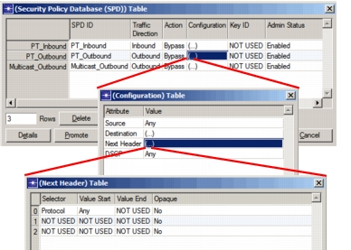
When the HAIPE version is configured as 3.0 or higher, there is one final configuration required to enable the use of IGMP: the PT SPD and the CT SPD. A Bypass policy must be configured in the outbound and inbound directions for both SPDs to allow the IGMP control traffic that is sent/received in the clear to be appropriately processed. The best way to do this is to create policies that match on any protocol, as shown in the PT SPD example below.
Note: The PT SPD and CT SPD tables are found on the Security > HAIPE Parameters > Interface Information attribute.
Figure 158: Configuring PT Security Policy for IGMP
HAIPE Interfaces
Each HAIPE device has two physical interfaces: Plaintext (PT) and Ciphertext (CT). The Interface Information attribute is where both interfaces (and their corresponding features) are configured. The following table provides a description of each of these attributes and notes when the attribute needs to be configured.
Table 81: HAIPE Interface Attributes
| Attribute | When Required | Description |
|---|---|---|
| IP Routing Parameters > Interface Information > Address | Always required, if using IPv4 | Configures the IP address for the interface |
| IPv6 Parameters > Interface Information > Global Address(es) | Always required, if using IPv6 | Configures the IPv6 address(es) for the interface |
| IP Routing/IPv6 Parameters > Interface Information > MTU | Always required | Configures the MTU for the interface. No packet sent out this interface will be larger than the value configured for this attribute. |
| Type | Always required | Allows the ability to specify which of the interfaces is connected to the PT network and which is connected to the CT network. Normally, the default configuration will be used. |
| Default Route | When the next hop to use for traffic sent out this interface needs to be explicitly defined | Since the HAIPE does not partake in any IP routing, it needs to know who the next hop of traffic sent out each interface will be. The default route attribute specifies that and is used by ARP to determine the destination MAC address. If this attribute is left as Auto Assigned, then the IP device directly connected to this interface will be used as the next hop. If there are multiple IP devices directly connected to this interface, then one of them will be randomly chosen as the destination. If this is configured as Disabled, then the destination address of the packet being sent out this interface will be used as the next hop. |
| TTL | Optional for CT interface and not available for PT interface | Defines the value placed into the TTL field within the IP header for traffic sent from this interface. When left as Default, the IP standard value of 32 will be used. |
| Security Policy Database | Always required | Allows for the configuration of the SPD for the interface. If the SPD is left empty, then the Implicit Discard policy will ensure that any traffic traveling through the SPD is dropped. |
When sending traffic out the CT interface, the CT Default Route is always used as the next hop. When sending traffic out the PT interface, if the HAIPE version is 1.3.5 then the PT Default route will always be used as the next hop. However, if the HAIPE version is 3.0, then the LEPT is actually used to identify the next hop. This information may come from RIP or from the manual LEPT (for manual LEPT entries, if the Next Hop attribute is left configured as Use Default then the PT Default Route will be used).
The PT SPD and the CT SPD are used for different purposes and have different options when they are being configured. Additionally, the values available to configure for some of the attributes within each policy are dictated by the configuration of other attributes within that same policy.
Manual Security Association Database
The Manual Security Association Database (SAD) attribute provides the ability to configure manual security associations for a HAIPE device. As described in the earlier section on the SAD table structure, in order for two HAIPE devices to have two-way communication, two security associations (either manual or dynamically negotiated via IKE) are required on each HAIPE: one outbound and one inbound (recall that an SA is used for communication in one direction). The outbound SA on HAIPE_A and the inbound SA on HAIPE_B define a communication tunnel. Certain attributes within these two security associations configured on two different HAIPEs must match in order for that tunnel to work properly. The following table lists and defines the attributes for manual security associations that must match on both sides of the tunnel in order for communication to be possible.
Table 82: Manual SA Attributes Common Across SA Tunnel
| Attribute(s) | Description |
|---|---|
| SPI | Uniquely identifies a HAIPE communication tunnel. The SPI for an outbound security association on HAIPE_A and the corresponding inbound security association on HAIPE_B must match. Each SPI configured within the network should be unique. |
| CT Security Policies | As stated in the earlier section discussing the SAD table structure, the model implementation deviates slightly from the HAIPE MIB when it comes to linking the CT SPD to the SAD. This attribute is used to define which CT security policies should be used to determine whether traffic is allowed to use this SA (similar to the CT Security Policy attributes in the FFSA Table). For outbound SAs, this links to outbound security policies in the CT SPD. For inbound SAs, this links to inbound-SA security policies in the CT SPD. While these values do not necessarily have to match across both sides of the connection, the user must be careful to ensure that there is some sense of commonality. For example, if I have configured my outbound SA to link to outbound security policies that allow traffic with DSCP code AF21 to use the SA but have configured the inbound SA on the other side to link to an inbound-SA security policy that discards traffic with DSCP code AF21 I will have some problems. So again, while the policies do not have to match up perfectly, traffic allowed outbound should also be allowed inbound. |
| Direction | Specifies the direction of this SA (i.e. which direction traffic will be traveling when this SA is available). There must be an outbound SA configured on HAIPE_A and an inbound SA configured on HAIPE_B (both with the same SPI as mentioned above) in order for communication in the one direction to take place. |
| PPK Chain ID | Specifies the PPK Chain to use for this manual security association (links into the PPK Chain Table defined within the Key Configurations attribute). This string value must match on both sides of the connection. This value does not define the actual pre-placed key (PPK) itself since the model does not go into that level of detail; only to the PPK Chain ID level. |
| Transform ID/Suite Name | Specifies the transform to use for this manual security association (links into the Transform Configurations table attribute). While the actual strings configured for both sides of the tunnel do not need to match for this attribute (the names are only locally significant), the actual configuration of the transform (i.e. the cryptographic parameters) do need to match. |
The remaining attributes available for each manual security association are more locally significant since they define how the HAIPE handles traffic that is sent or received on the particular SA. A description of these additional attributes that make up a single security association, as well as when they are required to be configured (or available for configuration) are listed in the following table.
Table 83: Manual SA Attributes Locally Applicable
| Attribute(s) | Description |
|---|---|
| Peer Information | This attribute defines either 1) the CT destination address to use when creating the CT IP header for outbound SAs, or 2) the expected CT source address of the CT IP packet received for inbound SAs (when an inbound SAD lookup is done, a match is required for the SPI and the CT source address). In general, this attribute should be configured with the name of the HAIPE that the SA is peering with (the PT/CT address information of that peer will automatically be determined by the simulation). For multicast SAs, the outbound SA must be configured with the CT multicast address (in order to do this, a proper Multicast Address Mapping Table entry must be present which is why multicast configuration should be done before the manual SAD configuration). The inbound SA for that same outbound multicast SA should still point back at the HAIPE peer generating the traffic since the inbound SAD lookup is done using the source CT address (which will be the IP address of that HAIPE's CT interface). |
| Transport Mode Topology Table | This table is used when an inbound SA configured with a transport mode transform is processing traffic. When a packet is encrypted using a transport mode transform, the original PT IP header is stripped before being encrypted. Since the PT header is not available during inbound processing, the receiving HAIPE must recreate the original PT header so it can transmit a routable packet out the PT interface after decryption/decapsulation. The Transport Mode Topology Table provides the PT source and destination IP addresses which is used by the SA to recreate the PT IP header. |
| ToS Bypass DSCP Bypass ECN Bypass DF Bypass PHRD Configuration TFS Configuration Control Plane Signaling Bits |
These attributes all specify networking and traffic protection attributes that are available when configuring outbound security associations. Some of them are only available when the configured HAIPE version is 1.3.5 (i.e. ToS Bypass) while some of them are not available unless the version is 3.0 or higher (i.e. DSCP Bypass, ECN Bypass, PHRD Configuration). Control Plane Signaling Bits can old be enabled when the version is 3.1 or higher. The configuration of these attributes is optional as they are already configured with default values. |
| ECN Bypass Transmit PDUN Messages |
These attributes all specify networking and traffic protection attributes that are available when configuring inbound security associations. None of them are available unless the configured HAIPE version is 3.0 or higher. The configuration of these attributes is optional as they are already configured with default values. |
| Manual Path MTU | This attribute allows the user to manually define a Path MTU to use for this security association. Every security association has a Path MTU to use. The HAIPE IS specifies that Path MTU discovery can be supported. However, when this protocol is not available, this attribute is a way to specify that Path MTU value for the SA manually. If this attribute is left configured as Disabled, then the MTU configured for the CT interface will be used as the Path MTU. |
| Security Classification | Specifies the security level that is supported by this SA. This level must match the SA's configuration on the peer HAIPE, else the packets will be dropped by the receiving HAIPE. |
| RoHC Status RoHC Profiles RoHC - SPI of SA for Feedback RoHC Maximum Contexts RoHC Initialization and Refresh Timeout |
These attributes specify the configuration of Robust Header Compression (RoHC) for this SA. They are described in more detail under the RoHC attributes section. |
The model does not support the dynamic negotiation of transport mode security associations. Therefore, any transport mode SA required will need to be configured manually.
You can also use the following operation on the Protocols menu to create manual security associations: Protocols > IP > HAIPE > Create Security Association Between Selected HAIPEs.
You can also import the manual SAD using the "Protocols > IP > HAIPE > Import > Security Association Information" utility. Several example manual SAD import files are included with the HAIPE example project. These files are located in the <reldir>/models/std/example_networks directory and are named HAIPE-<Scenario Name>_SA_Import.csv. The format is listed in the following table.
Table 84: HAIPE Manual SAD Import Format
| Column Number | Attribute | Potential Values |
|---|---|---|
| 1 | HAIPE that SA is being imported for | <Node Hierarchical Name> |
| 2 | SPI | < integer value> |
| 3 | CT SPD ID(s) | Any< CT SPD ID> |
| 4 | Peer Information | <Node Hierarchical Name><CT IP Address> |
| 5 | SA Direction | Outbound Inbound |
| 6 | PPK Chain ID | <PPK Chain ID> |
| 7 | Transform ID/Suite Name | <Transform ID/Suite Name> |
| 8 | DSCP Bypass/ToS Bypass | Default Enable All Codes Enabled Disabled |
| 9 | ECN Bypass | Default Enabled-CN Enabled-AC Disabled |
| 10 | DF Bypass | Default Bypass Set Clear |
| 11 | Transmit PDUN Messages | Default Enabled Disabled |
| 12 | Transmit PHRD Messages | Default Enabled Disabled |
| 13 | Decrement TTL | Default Enabled Disabled |
| 14 | TFS | Default Use Default Configuration Disabled Variable Packet Length |
| 15 | Manual Path MTU | Disabled<Path MTU in bytes> |
Modeling Vendor-Specific HAIPE Implementations
The HAIPE IS was created to ensure interoperability between the HAIPE devices developed by different hardware vendors and does not specifically address all details required for implementation. These details were purposely left obscure to promote competition amongst the hardware vendors.
In general, the HAIPE model has been developed as a generic implementation of the requirements specified in the HAIPE Interoperability Specification (IS). However, a suite of attributes is available (under "HAIPE Parameters' Advanced Configurations") that will allow the user to configure hardware and performance limitations obtained via vendor published documentation and performance benchmarking as well as allow for the configuration of implementation or design choices (i.e. algorithm details). The common element shared by all of these attributes is that none of them are configurable via the standard HAIPE MIB or specified in the HAIPE IS.
Modifying the configuration of the attributes under "Advanced Configurations" is never required, but it is important to understand the potential impact they may have. The following table provides a brief description of some of the more important attributes as well as when their configuration will impact the behavior of the model.
Table 85: Important Advanced Configuration Attributes
| Attribute | Impact | Description |
|---|---|---|
| Maximum Number of Security Associations Stale SA Interval Stale SA Removal Style |
When doing studies involving IKE and a very large number of HAIPEs in a network | If an attempt to add a dynamic SA (via IKE) is made and the Maximum Number of Security Associations has already been reached, the SAD will be searched for a stale SA. A stale SA is defined as a dynamic SA that has not been used within a specific time window (specified by the Stale SA Interval). If there are any stale SAs in the SAD, then one of those stale SAs will be removed to make room for the new SA. If there are no stale SAs in the SAD, then the new SA that is being added will not be added. The algorithm to use when removing a stale SA is based on the Stale SA Removal Style configuration. |
| Local Prefix Timeout Style | When doing studies involving local enclave dynamic discovery | Specifically deals with the behavior of the HAIPE when routes are being purged from the RIP route table. When a failure occurs, the expiration of the route invalid timer will cause the metric of the route which the timer references to be set to 16 (invalid). However, it will not remove it from the RIP route table. This does not happen until the garbage collection timer expires (typically an additional 30 seconds later). In the model, the LEPT is informed of the cost change after the invalid timer expires but does not remove it. Additionally, since that cost means nothing to the LEPT it sees that route as still being valid, just with a worse cost. So, the addition of this configurable attribute will allow the user to decide whether the Garbage Collection Timer is actually used or not. |
| Remote Prefix Timeout Style | When doing studies involving remote enclave dynamic discovery | Specifies the behavior of the HAIPE when the prefix lifetime for a dynamically learned prefix expires. The following options are available: Remove After Query: A prefix lifetime expiration will trigger a new solicitation-query message for the prefix of the corresponding entry. The result of that query will determine whether the expired prefix actually gets removed from the PEPT. If the query fails, then the entry is removed. If the query is successful, the behavior depends on the route returned by the query. If it matches the existing entry, then the prefix lifetime of the original entry is simply reset. If the query returns a different route, then the original entry is removed and replaced with the new one. Remove Immediately: A prefix lifetime expiration will result in the expired entry being immediately removed from the PEPT. The next packet destined for that network will trigger a solicitation-query. |
| Solicitation Backoff Interval Exchange Backoff Interval |
When doing studies that include dynamic mechanisms (IKE and/or Discovery) and failure/recovery modeling | When a dynamic discovery query or IKE exchange is initiated and fails, there is a backoff timer started so that additional queries/exchanges targeting the same IP address will not flood the network. These attributes configure that amount of time between when one of these exchanges fails and when the next can begin. |
| Vendor ID Payload | When doing studies involving IKE and measuring the overhead of HAIPE protocols on the CT network | This attribute is important because it affects the size of HAIPE IKE messages 1 and 2. By default, the Vendor ID Payload will be part of both of those messages. However, the user has the option to not include that payload with HAIPE IKE messages 1 and 2 and thus decrease their size. The HAIPE IS does not require the inclusion of this payload in HAIPE IKE messages 1 and 2 but does allow HAIPE hardware vendors to use this payload to identify particular devices for proprietary purposes. The model does not actually use this payload for anything in particular. |
The Crypto Processing Delay attribute allows for the configuration of delay information that impacts the time it takes for a packet to be processed by a HAIPE. In general, this attribute allows for simulating the time it takes for a packet to travel through all portions of the cryptographic core (SPD lookups, table lookups, encryption/decryption, etc.). The delay can be computed using an exponential distribution (where all packets are randomly given a delay regardless of the properties of that packet or the state of the HAIPE device) or can be computed using a more granular means via the import of a CSV file. The CSV file has the following format:
Figure 159: File Format for Crypto Processing Delay
#Jitter Included
<YES/NO>
#Packet Loss Included
<YES/NO>
						PACKET_SIZE_BYTES								PACKET_SIZE_BYTES
<DATA_RATE>						<DELAY>;<JITTER>;<PKT_LOSS>								<DELAY>;<JITTER>;<PKT_LOSS>
<DATA_RATE>						<DELAY>;<JITTER>;<PKT_LOSS>								<DELAY>;<JITTER>;<PKT_LOSS>
Where
<DATA_RATE>is in bits per second<DELAY>is the average delay in milliseconds<JITTER>is the average jitter in milliseconds<PKT_LOSS>is the average packet loss as a percentage
In the file-based configuration, the size of the packet and the current data rate observed by the HAIPE determine the computed delay and jitter (optionally). These values also determine whether the packet is dropped (optionally).
The configured delay values are only locally significant; they can be configured with different files across multiple HAIPE devices in the same scenario.