Model Attributes: TCP
Each node with TCP as one of its contained protocols, provides an attribute, called “TCP Parameters”, to specify TCP configuration parameters. There are several preset values available for this attribute to allow you to choose from different TCP “flavors”:
Figure 546: TCP Parameters—Architecture-Specific Settings
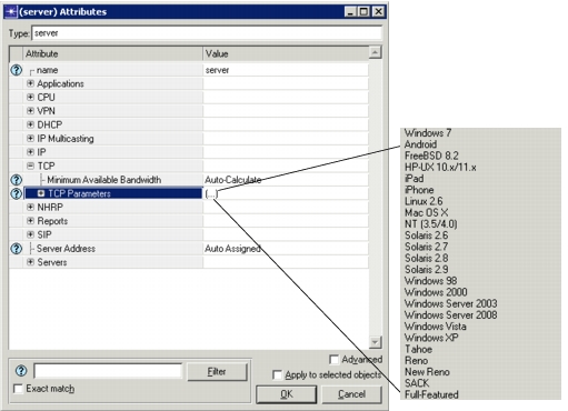
Values for most of these settings have been referenced from the following URL:
http://www.psc.edu/index.php/tcp-performance-tuning
The “TCP Parameters” attribute itself consists of many sub-attributes (these can be inspected by using the “Edit...” option for its value), as shown below.
Figure 547: TCP Parameters—Configurable
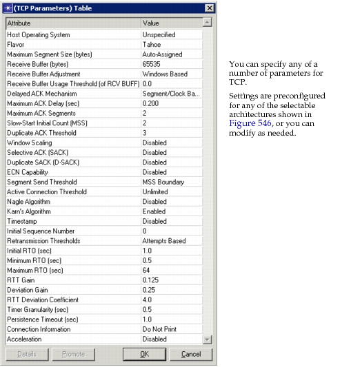
Some of the important TCP model attributes are:
- Minimum Available Bandwidth: Specifies the bandwidth of the bottleneck link between two peers. This setting is used when “Receive Buffer (bytes)” is set to Auto-Tuning, which allows TCP to select the appropriate size of the receive window based on the network conditions.You may set this parameter in one of the following ways. You may manually enter a value, in bits per second (bps), or select an option from the drop-down pick list, as described below:
- Auto-Calculate—Uses the bandwidth of the first interface of the node
- Choose a predefined value (e.g., WLAN 11n, WiMAX, LTE, 100baseT). For wireless technologies, a predefined value is used to simulate realistic values by multiplying a theoretical bit rate value of the corresponding technology by 0.6.
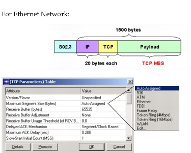
- Maximum Segment Size: Defines the largest amount of data that will be transmitted as one TCP segment. Choosing a good MSS value is important because if MSS is small, network utilization may be low; on the contrary, if MSS is large, it degrades performance as it results in creation of many IP datagrams, which cannot be acknowledged or retransmitted independently. Typically, this value should be set equal to the maximum size that the “MAC” layer can handle, minus the size of TCP and IP headers. Setting this attribute to “Auto-Assigned” automatically guarantees that it is configured optimally for the data link layer over which TCP is operating.
Figure 548: Setting Maximum Segment Size
-
Maximum ACK Delay: Defines the longest time that a TCP connection process waits to send an acknowledgment (ACK) after receiving data. Note that TCP does not send an ACK the instant that it receives data. Instead, it delays the ACK, hoping to have data going in the same direction as the ACK, so the ACK can be sent along with the data (called ACK piggybacking).
This attribute can significantly influence end-to-end delay when a TCP process is primarily receiving (and not both sending and receiving) data. This is so because the TCP connection process waits for this timer to expire before sending an ACK. Higher values generally result in higher application response times. However, a low value may result in too many dataless acknowledgments, adding to network load.
To determine this value, consult your system's configuration or examine a network analyzer trace. Typically, this value is set to 200 msec, and the ACKing procedure works in conjunction with the “Delayed ACK Mechanism” attribute setting.
-
Maximum ACK Segments: The maximum number of segments after which a dataless ACK will be sent. This attribute is used only if the “Delayed ACK Mechanism” attribute is set as “Segment/Clock Based”.
-
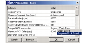
Delayed ACK Mechanism: This attribute setting controls how the delayed “dataless” acknowledgments are sent by the TCP connection process. The most common implementation is “Segment/Clock Based”, wherein dataless ACKs are generated upon receipt of every other received TCP segment or at the maximum delay timer expiration, whichever happens first.
-
Receive Buffer and Receive Buffer Usage Threshold: This is another important parameter to which the application delay is sensitive. It effects the TCP connection’s window size. Note that the window size is the amount of buffer space available in the receive buffer. This parameter determines when data should be transferred from the TCP's receive buffer to the application, thereby allowing the receive window to open further. Values are expressed as a fraction of the receive buffer size using a value between 0.0 and 1.0. In general, higher values will result in higher response times for your application (i.e., slower application).
As the receive buffer (RCV_BUFF) starts getting filled, the advertised window starts decreasing, thus limiting the flow of traffic from the peer TCP connection. A higher threshold setting will keep data in the receive buffer for a longer duration, thereby causing increased delays. Since the threshold is a fraction of the receive buffer, the effect of this setting is more observable at smaller receive buffer sizes. A low value for this setting allows data from the receive buffer to be transferred to the application more often; as a result, the advertised window is always close to the full window.
This attribute is hard to determine exactly. Looking at your network analyzer's trace output, examine how the receive window size varies each time data is received by the host of interest. Your analyzer's output may show this value as RWIN or a similar variable name. If the receive window remains at or close to its maximum value each time data is received, then the Application Layer is absorbing data from TCP quickly and you should use a low number such as 0.0 or 0.1 for value of the usage threshold. Conversely, if the receive window drops each time data is received, only to open up again after several segments are obtained, then a higher value should be entered for the usage threshold. For example, if the maximum receive window is 16K bytes, and the advertised receive window routinely drops to 8K bytes before moving back to 16K bytes, a value of 0.5 would be appropriate for the usage threshold. While many UNIX systems implement a value of 0.5 for this parameter, Microsoft Windows systems are more accurately modeled with a low value, such as 0.0. However, you should analyze actual trace output to determine the value of this important parameter.
Certain operating systems allow for auto-tuning of the receive window size. This allows the receiver to modify the receive window based on changing conditions. With a value of “Auto-Tuning”, the exact value of this parameter will be based on the round-trip time (RTT) and the bandwidth of the link so that the sender may fully utilize the pipeline. The maximum allowable value is 4 MB.
Note: A value of “Auto-Tuning” will also enable the Window Scaling and the Timestamp options, if they are disabled.
-
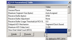
Slow-Start Initial Count: Specifies the number of MSS-sized TCP segments that will be sent upon slow-start. This also represents the value of the initial congestion window (or “cwnd”). In some TCP implementations, it is set to one MSS, indicating that every time TCP performs slow-start, it will start with one segment as its initial window. RFC-2414 is an experimental document that describes how critical it is to tune this value. It upper bounds this initial window as:
min [4 * MSS, max (2 * MSS, 4380 bytes)]
Other implementations set the initial count to two. This helps in reducing the overall end-to-end delay for data transfers, especially if the data size stays within the slow-start threshold. models allow you to choose from a list of possible values, including using the algorithm defined in RFC-2414:
-
ECN Capability: Enables addition of explicit congestion notification (ECN) to IP. For ECN to work actively, you must set this attribute to “Enabled” and also configure IP QoS queuing on the QoS Attribute Config utility node, as follows:
a) Configure a global queuing profile (such as FIFO or WFQ) on the QoS Attribute Config utility node. b) On the queuing profile’s RED Parameters attribute, set either “RED with ECN” or “WRED with ECN” (the RED Status and CE Marking attributes will both be “Enabled”). c) Apply the queuing profile to the desired network interfaces by choosing Protocols > IP > QoS > Configure QoS... (Alternatively, you can apply the profile manually.)
For more information on how to configure QoS queuing, see “Model Attributes: IP QoS” in the IP Model Guide.
Protocol-Specific Algorithms
The following algorithms are available in a given TCP implementation:
-
Window Scaling—Indicates whether this host sends the Window Scaling enabled option in its SYN message, as detailed in RFC 1323. For Window Scaling to work, this attribute must be set to “Enabled” at the client host, and either set to “Enabled” or “Passive” at the server host. If the client host has the attribute set to “Passive”, Window Scaling is disabled at the server host.
-
Selective ACKnowledgment—Indicates whether this host sends the Selective Acknowledgement Permitted option in its SYN message, as detailed in RFC 2018. When SACK is enabled or set to “Passive” on the server, the server will respond with a SACK when the client requests it.
Note: If the client has this attribute configured as “Passive”, the server will automatically be configured as “Disabled”.
-
Duplicate SACK (D-SACK)—Indicates whether this host uses the SACK option on the outgoing packets that acknowledges duplicate received packets, as specified in RFC 2883. When D-SACK is enabled, and the TCP receiver gets a duplicate packet, then this information is reported back to the sender using the first block of the SACK option field. In this way, the sender is able to recover the values of the congestion window and the slow start threshold that existed before the retransmission.
Note: Note that if SACK is set to Disabled, Duplicate SACK will also be set to Disabled.
-
Nagle’s Algorithm—Indicates whether this algorithm is enabled, as described in RFC 1122. Nagle's algorithm prevents smaller than MSS-sized segments to be sent while waiting for an ACK for previously sent data.
-
Karn’s Algorithm—Indicates whether this algorithm is used for calculating retransmission timeout (RTO) values to avoid retransmission ambiguity.