Model Attributes: IP QoS
This section provides a brief overview of the attributes used most often when configuring IP QoS. For more information on an attribute, click on the help icon next to an attribute’s name in the Attributes dialog box.
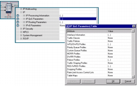
All IP nodes—such as routers, workstations, and servers—have an IP QoS Parameters compound attribute that is used to specify the IP QoS configuration on the node. The IP QoS Parameters attribute groups configuration settings into QoS profiles.
Figure 275: IP QoS Parameters Attribute
The IP QoS Parameters > Interface Information compound attribute specifies which QoS schemes and respective QoS profiles are used at particular IP interfaces and sub-interfaces. In the following figure, the Ethernet 1/1 interface uses WFQ scheduling, Inbound Policing, and Congestion Avoidance.
Figure 276: IP QoS Parameters: Interface Information
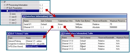
The Buffer Size (Bytes) interface sub-attribute specifies the total physical memory available on the interface. Reserved Bandwidth Type and Maximum Reserved Bandwidth are used for setting the interface processing rate in either absolute terms (bits per second) or relative terms (percentage of the attached link speed).
The Maximum Reserved Bandwidth attribute controls the processing rate at which the IP interface forwards packets (IP datagrams) to the lower layers.
When setting the IP interface rate it is important to consider the lower-layer overheads each IP datagram will incur as it travels from the IP interface to the link transmitter. Because the overheads increase the size of the packet, the link transmitter will experience a larger load than the IP interface. This effect is more pronounced in small packets.
Consider, for example, the G.729 voice application, which has rather small packets (10 bytes at application layer, 38 bytes at the IP layer including the IP/UDP overhead). For a simple point-to-point IP interface, the IP datagram acquires an additional 7-byte PPP overhead on its way to the link transmitter. The packet size increase (from 38 bytes to 45 bytes) represents a 19% increased load at the transmitter (compared to the IP interface). Therefore, if the IP scheduler forwards packets at a rate equal to 100% of the link rate, the utilization at the transmitter will be 119%. To avoid this congestion at the transmitter you need to account for the 19% increase in load by reducing the rate of the IP interface scheduler (to 75-80% of the link speed, for example).
The default value of 75% for the Maximum Reserved Bandwidth attribute works well in most cases, but you can calculate the appropriate IP interface rate more precisely using the example above as a guide.
QoS profiles contain detailed information about the QoS mechanism settings. For example, a WFQ profile specifies the number of queues used, their respective weights, and queue size limits. There are two types of QoS profiles.
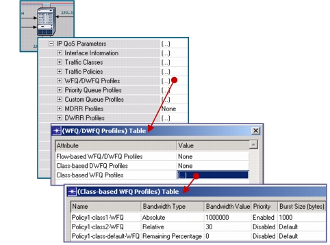
- Local profiles: Configured locally on the node under the IP QoS Parameters attribute. These profiles are local to the node and cannot be referenced on other nodes in the network.
Figure 277: Local QoS Profiles
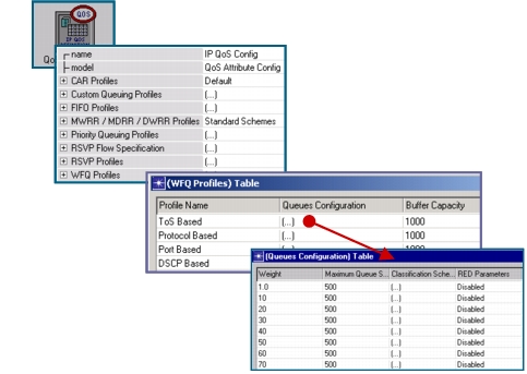
- Global profiles: Configured on the global QoS Attribute Config utility node. These profiles are stored in a global database and can be referenced network-wide on any node. Global profiles are supported for discrete event simulation only. Currently, flow analysis does not support global QoS profiles.
Figure 278: Global QoS Profiles