Stereoscopic Displays
Stereoscopic display produces realistic three dimensional imagery by showing each of the viewer’s eyes a different image, rendered from that eye’s point of view. A stereoscopic display requires a system that can render two channels, one for each eye, and a method of displaying the correct channel to the correct eye of the viewer. Three common display methods are active stereo, polarized display, and anaglyphic stereo. OpenSceneGraph can support all three of these methods, and since 3D Network Visualizer uses OpenSceneGraph for most of its rendering, all three should be possible in 3D Network Visualizer.
- Active Stereo: In an active stereo setup, frames are alternated on the display for the left eye and the right eye, and a pair of shutter glasses blocks light to either the left or right eye in synchronization with the display. This method requires hardware support to synchronize the glasses to the display, along with a graphics card capable of quad buffering, and a display that can refresh at twice the desired frame rate. Active stereo should be possible with 3D Network Visualizer, but has not been tested.
- Anaglyphic Stereo: Anaglyphic stereo is the cheapest and simplest method to use. A typical setup is a display showing a red channel and a cyan channel simultaneously, along with a pair of glasses with one red lens and one cyan lens for the viewer. This will work with no special hardware aside from the inexpensive glasses. It is also the simplest method to set up in 3D Network Visualizer, requiring only that some OpenSceneGraph environment variables be set.
- Polarized Stereo: A polarized display shows the frames for both eyes simultaneously, but with their light polarized in different directions. The viewer wears glasses that have lenses polarized to match the two different frames, allowing each eye to see only the frame intended for it. Polarized stereoscopy requires some specialized equipment to display the images with the correct polarization. One simple method for producing this kind of display is to use two projectors with polarizing filters, projecting onto a rear projection screen. Monitors are available that can polarize the two frames. It is easy to configure a polarized display with 3D Network Visualizer.
Configuring Anaglyphic Stereo
You can configure OpenSceneGraph for anaglyphic stereo rendering through environment variables. To use 3D Network Visualizer in anaglyphic mode, run it with the environment variables described in Table 2.
Table 2: Environment variables for anaglyphic stereo
| Environment Variable | Description | Default |
|---|---|---|
OSG_STEREO |
Turn stereo on. | ON |
OSG_STEREO_MODE |
Use anaglyphic stereo when in stereo. | ANAGLYPHIC |
OSG_SCREEN_DISTANCE |
Specifies the distance, in meters, that the viewer is from the screen. | 0.50 |
OSG_SCREEN_HEIGHT |
Specifies the height of the image, in meters, on the screen. | 0.26 |
OSG_SCREEN_WIDTH |
Specifies the width of the image, in meters, on the screen. | 0.325 |
OSG_EYE_SEPARATION |
Specifies the eye separation (interoccular distance). | 0.06 |
For more information, pleases see the OpenSceneGraph documentation at http://www.openscenegraph.org/projects/osg/wiki/Support/UserGuides/StereoSettings.
Configuring Polarized Stereo
You can configure polarized stereo by taking advantage of 3D Network Visualizer’s ability to produce multichannel displays. You configure one channel per eye. Each channel renders with a camera that is at a slight offset from the other channel’s camera to represent the spacing between the viewer’s eyes.
Varying the eye spacing and focal length can produce different effects, and the best values may depend on what the viewer is looking at. Figure 24 shows an example configuration.
Figure 24: Polarized stereo channel configurations
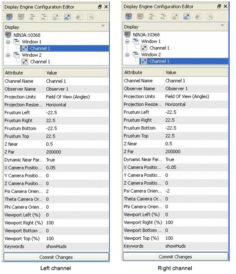
Procedure 24: Computing Channel Configuration Values for Polarized Stereo
- Pick a focal length,
L. Objects at this distance will appear to be in the plane of the display. Objects that are further away will appear behind the display, and objects closer will appear in front of it. - Pick an eye spacing,
E, to represent the distance between the viewer’s eyes. Human eyes are typically about 0.063m apart (http://www.cl.cam.ac.uk/~nad10/pubs/EI5291A-05.pdf). - Set the X Camera Position values to
–E/2meters for the left channel andE/2meters for the right channel. - Set the Psi Camera Orientation values to
–arctan(E/2)/Ldegrees for the left channel andarctan(E/2)/Ldegrees for the right channel.