Changing a Channel’s Attributes
You can change the following attributes of a channel:
- Channel Name
- Observer Name
- Projection Units – field of view, in angles, or database, in meters
- Projection Resize Policy – fixed, vertical, or horizontal
- Frustum (Left, Right, Top, and Bottom) (field of view)
- Z Near and Z Far (clipping planes)
- Dynamic Near Far Planes
- Parent Channel
- Camera Position Offset (X, Y, Z)
- Camera Orientation Offset (Psi (heading), Theta (pitch), Phi (roll))
- Viewport (Left, Right, Bottom, Top)
- Keywords – user-defined keywords to associate with the channel, for example, “showCockpits”.
Procedure 16: Changing the Attributes of a Channel
-
Select the channel in the Display Engine Configuration Editor Panel.
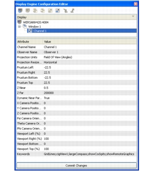
A list of attributes is displayed at the bottom of the editor (Figure 11).
Figure 11: Channel attributes
-
Click the value of the attribute that you want to change.
-
To change a numeric value, type a new value or use the spin control to change the value. To change the Observer Name, Project Units, Projections Resize Policy, or Parent Channel, select a value from the drop-down list. To change the Channel Name, type a new name. (For details about some of these attributes, please see the sections that follow this one.)
-
Click Commit Changes.
The window is updated.
Setting the Clipping Planes
To improve performance, the graphics engine does not render anything that falls outside of a specified range of distances from the observer. This range is determined by the near and far clipping planes.
By default, 3D Network Visualizer uses dynamic clipping planes. The near and far clipping values are determined based on the altitude of the observer. You can disable dynamic clipping planes and set the clipping planes manually with the Z Near and Z Far attributes of a channel.
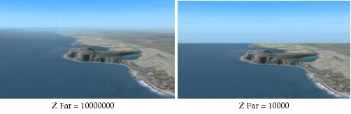
Figure 12 illustrates the effect of changing the Z Near value. Figure 13 illustrates the effect of changing the Z Far value.
Figure 12: Near clipping
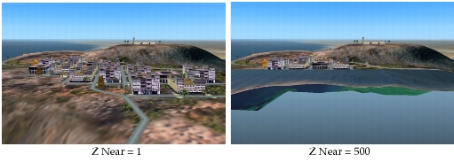
Figure 13: Far clipping
Procedure 17: Using Clipping Planes
- To enable or disable use of dynamic clipping planes, set the Dynamic Near Far Planes attribute to True or False.
- To change the near clipping plane, edit a channel’s Z Near attribute. To change the far clipping plane, edit the Z Far attribute.
Specifying the Projection Resize Policy Attribute
The Projection Resize Policy determines how a channel behaves when you resize it. The options are:
- Fixed: Keep the aspect ratio the same regardless of how the window is resized
- Horizontal: Maintain the horizontal aspect ratio when the window is resized
- Vertical: Maintain the vertical aspect ratio when the window is resized.
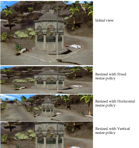
Figure 15 illustrates the effect of different resize policies, as follows:
- In the window with the fixed resize policy, all of the visual data in the initial view is still in the resized view, although the vertical dimensions are distorted.
- In the window with the horizontal resize policy, the field-of-view is widened to maintain the correct aspect ratio of the visual data.
- In the window with the vertical resize policy, the field-of-view is shortened.
You can change the projection resize policy for individual channels by editing the Projection Resize Policy attribute. You can also change the projection resize policy for all channels.
Procedure 18: Changing the Projection Resize Policy for all Channels
-
Choose Settings > Display.
The Display Settings dialog box opens.
-
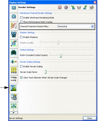
Select the Render Settings page (Figure 15).
Figure 14: Display Settings, Render Settings page
-
Select an option on the Channel Projection Resize Policy drop-down list.
Figure 15: Effect of different projection resize policies
Changing a Channel’s Frustum (Field of View)
The field of view setting affects perspective in a manner similar to a camera lens.
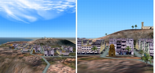
A wide field of view creates an effect like that of a wide-angle lens. Objects appear smaller and farther away from the observer, since the observer coverage spans a wider area. Depth distances between objects become exaggerated.
A narrow field of view creates an effect like that of a telephoto lens. Objects appear larger and closer to the observer, and the overall scene depth appears flattened. The distances between objects appears compressed.
Figure 16 illustrates different field of view settings. The view on the left has frustum values -30, 30, -30, 30. The view on the right has the frustum values ‑10, 10, ‑10, 10.
Figure 16: Field of view
To change a channel’s field of view, edit the frustum values in its attributes list.
Changing the Viewport
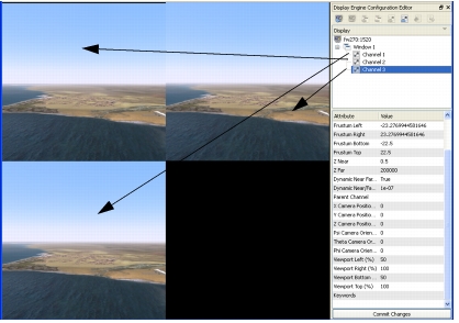
When you change the viewport of a channel, you change the portion of the window in which the channel is displayed. This does not change the extents of the scene. A narrow viewport compresses the scene width. A short viewport compresses the height. Figure 17 shows a window that has three channels, each with a different viewport. (The arrows show which portion of the window corresponds to each channel.) Notice that each channel has the same field of view.
Figure 17: Window with three channels and three viewports
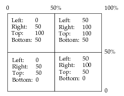
Viewports are specified as a percentage of the window from left to right and top to bottom. Figure 18 shows the percentage allocation for the viewports in Figure 17.
Figure 18: Viewport configuration
Note: When you change viewports, the window might not completely refresh. To see the changes, resize the window.