Introduction to 3D Network Visualizer Object Modeling
3D Network Visualizer can apply various types of visual effects to a model, such as trailing effects, height-above-terrain lines, track histories, and so on. Some of these effects are appropriate to a particular projection, some are available for both projections. Visual effects are implemented using visualizers.
Visual effects are managed by the integration of schemas, model definitions, element definitions, and model mapping.
- A schema is a set of parameters for a scene element (such as an entity). 3D Network Visualizer uses schemas to validate model definitions.
- A model definition specifies values for the required and optional parameters for an instance of a schema. For example the model definition for an M1A2 tank is an instance of the Entity schema. The model definition for a lifeform is an instance of a DiGuyCharacter schema. Of particular importance, a model definition specifies the 3D model to be used to represent an element in the scene.
- Element definitions (where elements can be entities, tactical graphics, or interactions) configure visual definition schemas on scene elements.
- Model definitions are associated with particular entity types by mapping an element definition to an entity type enumeration.
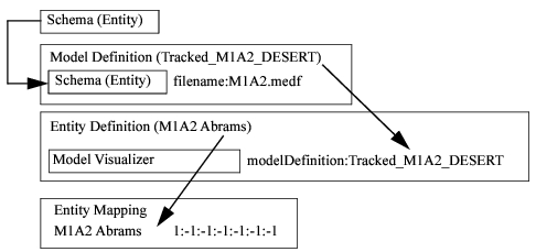
Figure 55 illustrates these relationships using an M1A2 entity. The model definition called Tracked_M1A2_DESERT uses an Entity schema. One of the parameters of the schema is the filename, which for this model definition is defined as M1A2.medf. The entity definition called M1A2 Abrams has a Model Visualizer. The modelDefinition attribute in the visualizer is specified as Tracked_M1A2_DESERT, which means that it will use the M1A2.medf model. The entity type 1:-1:-1:-1:-1:-1:-1 is mapped to the M1A2 Abrams entity definition. So, when 3D Network Visualizer discovers an entity with the enumeration 1:-1:-1:-1:-1:-1:-1, it will look up the M1A2 Abrams entity definition, which will tell it to use a Model Visualizer for this entity that uses the Tracked_M1A2_DESERT model definition, which specifies that 3D Network Visualizer use the M1A2.medf model to render the entity in the scene.
Figure 55: Element definitions and model mapping
To apply these abstract concepts to the concrete goals of a typical 3D Network Visualizer user, we could say that:
- If you want to visualize a completely new class of objects in 3D Network Visualizer, such as a celestial body, you would need to create a schema that specifies its parameters. If you want to change the parameters of an existing object, such as an entity, you would edit its schema. For details, please see “Creating and Editing Schemas“ on page 324.
- If you want to add a new instance of an object, such as a star, you would create a model definition using the celestial body schema and specify its parameters. If you want to change an element definition by, for example, changing the model displayed for it, you would edit its model definition. For details, please see “Creating and Editing Model Definitions“ on page 328.
- If you want your scene element to have visual effects, you would add appropriate visualizers in the entity definitions page or a specialized page. If you want to change the visualizers on an existing scene element, such as an entity, you would edit its entity definition. For details, please see “Creating and Editing Element Definitions“ on page 333.
- Finally, if the new object will be displayed based on simulation data received over the network, you must map it to an entity enumeration. For details, please see “Mapping Models to Entities and other Scene Elements“ on page 315.
Entity, Object, and Effects Models
3D Network Visualizer includes 3D models for vehicles, lifeforms, environmental objects, and effects. The models are in a compressed, encrypted format (extension .medf).
Note: 3D Network Visualizer includes a utility, the MEDF Tool, that lets you encrypt files in MEDF format. You cannot use it to decrypt encrypted files. For more information, please see “Compressing Model Files“ on page 321.
You can provide your own models if they are in one of the following supported formats:
- OpenFlight
- 3ds
- OBJ
Model Sets
3D Network Visualizer provides the following model sets.
- 3D Models. Realistic 3D models. This is the default model set for the Stealth observer mode.
- 3D Colorized Models. 3D colorized models are cartoon-like models that create an exaggerated notional view of the world. This is the default model set for XR observer mode.
Table 4-1 lists the 3D Network Visualizer model sets and the 3D Network Visualizer applications that support them.
Table 32: 3D Network Visualizer model sets
| Model Set | Application |
|---|---|
| 3D Models | 3D Network Visualizer 3D Network Visualizer XR |
| 3D Colorized Models | 3D Network Visualizer XR |
Note: The model sets available in each 3D Network Visualizer application are fixed. You cannot add model sets or edit the model sets provided.
For more information about observer modes, please see Observer Modes. For information about changing model sets, please see “Changing the Model Set“ on page 307.
Mapping Models to Entities and Objects
Model mapping is the process of associating an entity or other scene element with an element definition.
HLA objects are specified by an entity type enumeration. An entity type enumeration is a list of seven components as specified by the HLA RPR FOM. If none of the seven components contains a wildcard (-1) value, then the entity type refers to a specific entity. If some components contain a wildcard, then the entity type refers to a class of entities. A larger number of wildcards indicates a broader, more general class. For complete details about entity type enumerations, please see Enumeration and Bit Encoded Values for Use with Protocols for DIS Applications (DIS enumerations document). It is available at the IEEE World Wide Web site: http://shop.ieee.org/store and at the SISO web site: http://www.sisostds.org.
For more information about mapping models, please see Chapter 21 “Mapping Models and Effects” on page 315 and Chapter 22 “Model and Element Definitions” on page 323.