Mapping Models to Entities and other Scene Elements
Model mapping is the process of associating an entity or other scene element with an element definition.
HLA objects are specified by an entity type enumeration. An entity type enumeration is a list of seven components as specified by the HLA RPR FOM. If none of the seven components contains a wildcard (-1) value, then the entity type refers to a specific entity. If some components contain a wildcard, then the entity type refers to a class of entities. A larger number of wildcards indicates a broader, more general class. For complete details about entity type enumerations, please see Enumeration and Bit Encoded Values for Use with Protocols for DIS Applications (DIS enumerations document). It is available at the IEEE World Wide Web site: http://shop.ieee.org/store and at the SISO web site: http://www.sisostds.org.
When a 3D Network Visualizer application discovers an entity, it reads the enumeration and then displays the entity using the element definition that is mapped to the enumeration. (Element definition is a generic term that includes entity definitions, tactical graphic definitions, and other scene elements.)
You map models in the Entity Type Mappings dialog box. It has pages for mapping:
- Entity models
- Aggregate entity models
- Firing effects
- Detonation effects
- Tactical graphics
- Cockpit displays
The mapping process is the same for all model types. You can add new model mappings, edit existing model mappings, and delete mappings.
Note: You can map more than one element definition to an entity type. If you do this, when entities of this type appear in a simulation, 3D Network Visualizer randomly assigns one of the element definitions to the entity.
Note: The procedures in this section are for entities (and hence refer to entity definitions). However, the procedures are the same for all of the pages on the Entity Type Mappings dialog box.
Adding a Model Mapping
This procedure describes how to map an element definition to an entity type enumeration. The element definition must already exist. The procedure is the same for any page on the Entity Type Mappings dialog box.
Procedure 112: Adding a Model Mapping
-
Choose Settings > Entity Type Mappings. The Entity Type Mappings dialog box opens.
-
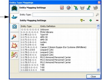
Select the Entity Mapping Settings page (Figure 102). The page shows a list of entity type enumerations in the Entity Type column. The entity definition mapped to the entity type is listed in the Entity Definition column. By default, the list of entity types is filtered to just show entities.
Figure 102: Entity Mapping Settings page
-
Click the Add icon (
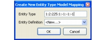
 ). The Create New Entity Type Model Mapping dialog box opens (Figure 103). It lists a default entity type enumeration.
Figure 103: Create New Entity Type Model Mapping dialog box
-
In the Entity Type text box, type the enumeration you want to map to a model. (Separate each value with a colon(:).)
-
In the Entity Definition drop-down list, select the element definition that you want to map to this entity type.
-
Click OK.
The new model mapping is added to the list.
If you add a model mapping in 3D Network Visualizer, you must also add it in Riverbed Modeler so that you can map nodes to the 3DNV model. See "Customizing Node/Entity Mapping" on page 83 for details.
Editing a Model Mapping
This procedure describes how to edit a model mapping for an entity. The procedure is the same for any page on the Entity Type Mappings dialog box.
Procedure 113: Editing a Model Mapping
-
Choose Settings > Entity Type Mappings. The Entity Type Mappings dialog box opens.
-
Select the Entity Mapping Settings page (Figure 102).
-
Select the model mapping that you want to edit. If you know the entity enumeration that you want to edit, you can type the enumeration in the Entity Type text box and click the Search icon (
 ). 3D Network Visualizer highlights the entry for that enumeration if it is present.
-
To change the enumeration associated with an element definition:
4.1 In the Entity Type column, click the enumeration to make it editable. 4.2 Change the values of the enumeration. 4.3 Click someplace else in the window.
-
To change the element definition associated with an enumeration:
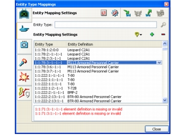
5.1 Optionally, filter the list of available element definitions. (For details, please see Filtering the Element Definition List.) 5.2 In the Entity Definition column, click the element definition to make it an editable list (Figure 104). 5.3 Select the new element definition from the drop-down list. 5.4 Click someplace else in the window.
Figure 104: Editable entity definition
Filtering the Element Definition List
You can filter the list of element definitions that are available in the drop-down list for mapping to entity types.
Procedure 114: Filtering the List of Element Definitions
- On any page of the Entity Type Mappings dialog box, click the Filter icon (
 ). A menu is displayed. A check mark indicates the type of element definition that will be displayed when you make a element definition entry editable. (You may have to expand the hierarchy to see which elements are checked.)
- Select the element definition type that you want to see in the list or select All to see all element definitions.
Deleting a Model Mapping
The procedure for deleting a model mapping is the same for any page on the Entity Type Mappings dialog box.
Procedure 115: Deleting a Model Mapping
- Choose Settings > Entity Type Mappings. The Entity Type Mappings dialog box opens.
- Select the Entity Mapping Settings page (Figure 102).
- Select the model mapping that you want to delete. If you know the entity enumeration that you want to edit, you can type the enumeration in the Entity Type text box and click the Search icon (
 ). 3D Network Visualizer highlights the entry for that enumeration if it is present.
- Click the Delete icon (
 ).
If you delete a model mapping in 3D Network Visualizer, you might also want to delete it in Riverbed Modeler. See "Customizing Node/Entity Mapping" on page 83 for details.
How 3D Network Visualizer Maps DI-Guy Models
When 3D Network Visualizer discovers a lifeform entity on the HLA networks, it chooses the animations to play for a DI-Guy based on the lifeform's speed, position, and similar attributes. However, if 3D Network Visualizer receives a special DI-Guy state message (PDU) that dictates the lifeform's character, appearance, or animation, 3D Network Visualizer will no longer try to guess and will expect to be told how to render that lifeform for the remainder of the simulation.