eXpress Data Import
To do this tutorial, you need to configure the following preferences:
mod_dirstraffic_archive_dir
To configure the mod_dirs preference, do the following procedure.
Procedure 1: Configuring the mod_dirs Preference
-
If Modeler is not already running, start it.
-
Choose Edit > Preferences.
-
Select the mod_dirs preference by typing mod_dirs in the Search for field and clicking on the Find button.
-
Display the contents of the mod_dirs preference by clicking in the Value column.
-
Verify that the following paths are included:
<reldir>\models\std\tutorial_req\module\configs\baseline<reldir>\models\std\tutorial_req\module\configs\with_areas_broken
<reldir>is the directory where the software is installed. On Windows platforms, the default location is C:\Riverbed\18.6. -
If either path is not included, follow these steps to enter it:
- 6.1 Select the
<reldir>\models\std\tutorial_reqdirectory. - 6.2 Click Insert.
- 6.3 Enter the missing path and press Return.
- 6.4 Click OK to close the mod_dirs preference dialog box.
- 6.1 Select the
To configure the traffic_archive_dir preference, do the following procedure.
Procedure 2: Configuring the traffic_archive_dir Preference
-
Select the traffic_archive_dir preference by typing it in the Search for field and clicking on the Find button.
-
Select either of the two traffic archive directories from the list.
-
Open the traffic_archive_dir dialog box by clicking in the Value column.
Verify that this path is included:
<reldir>\models\std\tutorial_req\module\trafficIf necessary, insert a new line and enter the path.
-
Close the dialog box, then close the Preferences dialog box.
Introduction
In this scenario, Middletown Bell provides local phone service and Internet access to one million homes and businesses in its service area. The network currently uses the OSPF protocol in a flat configuration, but management is considering a hierarchical configuration. Your department’s current project is to determine the feasibility of this configuration.
Your goal in this project is to create an accurate model of the current network. To reach that goal you will
- Create a baseline network model by importing router configuration files.
- Use the Interface Assistant to solve problems related to the import.
- Examine the models to learn how Modeler processes the router configuration files and creates models with appropriate attributes.
- Import traffic for the network.
If you have Flow Analysis functionality, you can also do a final step—determine utilization of the links in your network.
Importing the Baseline Network
Follow this procedure to import the baseline network.
Procedure 3: Importing the Baseline Network
-
Choose File > New….
-
Select Project from the pull-down menu and click OK.
-
Name the project <initials>_OSPF_Analysis, and the scenario Baseline. (Include your initials in the project name to distinguish it from other versions of this project.) Click OK.
Result: The Startup Wizard opens.
-
In the Initial Topology dialog box, select Import from Device Configurations and click Next >.
Result: The Import Device Configurations dialog box appears.
-
Select Cisco under the Vendor column of the Import Device Configurations dialog box.
Result: You want to import Cisco configurations ONLY. Importing the router configuration files produces an up-to-date topology that includes accurately configured routers.
For this lesson, we have supplied a set of ready-made router configuration files.
-
5.1 Specify the directory path provided below by typing in the value field, or click Browse to navigate to the directory:
<reldir>\models\std\tutorial_req\ module\configs\baseline -
5.2 Make sure that the Include Subfolders value is set to No.
-
5.3 Make sure that the Create PVCs checkbox is selected.
-
5.4 If any files are listed under Model Assistant Files, remove them by clicking on each file and selecting NONE.
-
5.5 Click Import.
Modeler finds the device configuration files and starts to import them. While importing the files, Modeler checks your model directories for node models that match the devices you are importing. If Modeler does not find a matching node model for any device, it will create one during the import.
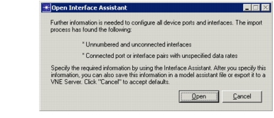
Result: The Open Interface Assistant dialog box appears. This happens when Modeler cannot find some of the information it needs from the configuration files being imported.
Figure 1: Required Information Not in File
-
-
Click Open.
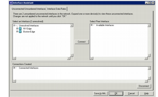
Result: The Interface Assistant dialog box appears.
Figure 2: Interface Assistant Dialog Box
Correcting the Configuration with the Interface Assistant
The Interface Assistant lets you specify information that is required to build a correct network. The information is saved in an model assistant (.ma) file and can be applied automatically when you import the router configuration again.
Follow this workflow when using the Interface Assistant:
- Examine the dialog box to understand the information presented
- Correct problems with unnumbered interfaces
- Correct problems with data rates
- Save the configuration in a model assistant file for future use
Examining the Dialog Box
Procedure 4: Examining the Dialog Box
- The tabs control which routers appear in the pane below it. There are two tabbed pages:
-
Unconnected Unnumbered Interfaces
-
Interface Data Rates
-
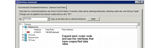
1.1 Click the Interface Data Rates tab and notice that four routers are listed. This means that Modeler did not find interface data rates in the router configuration import file for at least one interface on each of these routers. You will have to supply the information for these routers.
Figure 3: Devices with Unspecified Data Rates in the Interface Assistant Dialog Box
-
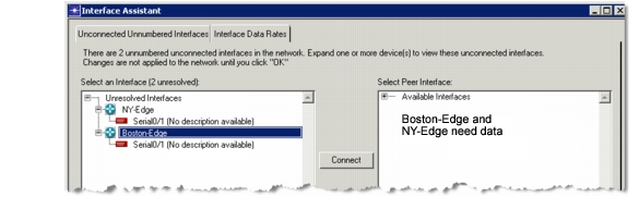
1.2 Click the Unconnected Unnumbered Interfaces tab and expand each router node. Notice that the router interfaces are shown in red. You will need to supply information about these two routers.
Figure 4: Unconnected Unnumbered Interfaces in the Interface Assistant Dialog Box
-
Correcting Problems with Unnumbered Interfaces
When importing a router configuration file, Modeler determines how a router is connected by analyzing the IP addresses of the router interfaces. If an interface has an unnumbered IP address, Modeler cannot determine where the interface should be connected and leaves it unconnected. You, as the network administrator, know how interfaces are connected and can give this information to Modeler.
Perform the follow procedure to supply the required information.
Procedure 5: Correcting Problems with Unnumbered Interfaces
-
On the Unconnected Unnumbered Interfaces tabbed page, expand the Boston-Edge router.
Result: The Serial0/1 interface highlighted in red is unconnected; the phrase No description available appears.
-
Select the port Serial 0/1 (no description available).
The NY-Edge router appears in the Select Peer Interfaces tree. NY-Edge also has an unconnected interface, so Modeler is suggesting that the two unconnected interfaces could be connected to each other.
This tutorial presents the simple case of two disconnected interfaces. In a real network, you might have multiple disconnected interfaces (all listed in the Devices pane) and you might have to examine the routers to determine the appropriate connections.
-
Expand the NY-Edge router in the Select Peer Interfaces tree.
-
Select the NY_Edge port Serial 0/1 (no description available).
-
Click the Connect button.
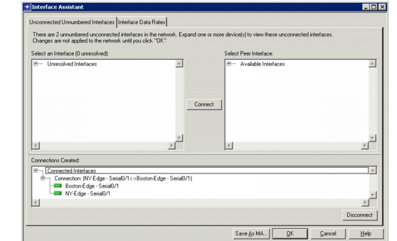
Result: Connections appear, along with their description, as green nodes under the Connections Created section. Both routers with disconnected interfaces are now connected.
Figure 5: Connected Interfaces in the Import Assistant Dialog Box
Correcting Problems with Unspecified Interface Data Rates
When Modeler imports a router configuration file, it determines the interface data rate either by obtaining the rate from the file or inferring the rate from the interface technology specified in the file. For example, an ATM interface is assumed to be an OC3 data rate.
When Modeler infers the data rate in this way, some routers might need to be corrected; these are listed in the Interface Assistant dialog box. This lets you change the data rate if the inferred rate is incorrect.
In this tutorial, you will change the rate for one interface and confirm the inferred rate for the other three interfaces. You will then save the model assistant file with this information.
Procedure 6: Correcting Problems with Unspecified Interface Data Rates
-
In the Interface Assistant dialog box, click the Interface Data Rates tab.
-
Expand all routers.
Result: The router interfaces with unspecified data rates appear red. Notice that each interface has an inferred data rate of SONET/OC3.
-
Change the data rate to SONET/OC1 for the Atlanta-Core interface, as follows:
-
3.1 Select the Atlanta-Core interface (ATM 0/0-Default Data Rate SONET/OC3).
-
3.2 In the Set drop-down list, select SONET/OC1 and click Apply.
Result: The new rate is applied to the interface and the router interface icon becomes green. The green indicates that you modified the router interface configuration.
-
-
Use SONET/OC3 data rate for the other three interfaces:
-
4.1 Select the SF-Core interface (ATM 0/0-Default Data Rate SONET/OC3).
-
4.2 Control-click to select the remaining two interfaces: DC-Core ATM1/0 and Denver-Core ATM0/0.
-
4.3 Reset the data rate to SONET/OC3 in the Set drop-down list.
-
4.4 Click Apply.
Result: The three remaining interface icons become green.
-
Saving the Configuration Details in a Model Assistant File
Follow this procedure to save the changes you made in a model assistant file.
Procedure 7: Saving the Configuration Details in a Model Assistant File
-
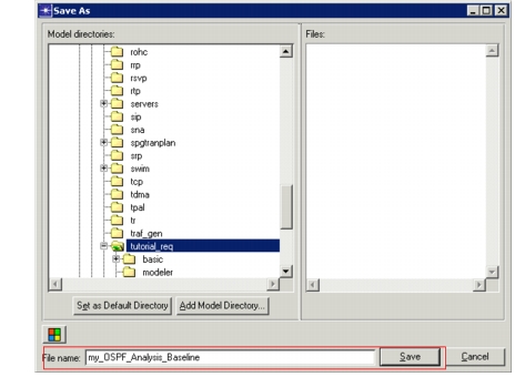
Click Save As MA... to specify the name for a model assistant file.
-
Name the file using your initials and the project and scenario names: <initials>_OSPF_Analysis_Baseline.
Figure 6: Specify Model Assistant File Name
-
Click Save.
-
Click OK to close Interface Assistant dialog box.
Result: Observe the information contained in the Import Summary (Concise) dialog box. You can click on View Details to see further information about the import.
-
When finished reviewing the import summary and details, click Close.
You can retrieve an import summary at a later time by right-clicking in the project workspace and selecting View Import Summary. Choose the import summary by the timestamp of interest.
Now you have a complete network topology. Modeler has chosen router and link models and configured model attributes appropriately, based on the information in the router configuration files. You have specified information that was not found in the configuration files during the import.
Specifying the Model Assistant File
You have already imported the topology and created an model assistant file that includes information needed to ensure a smooth import. In this section you will specify the model assistant (.ma) file you created.
Procedure 8: Specifying the Model Assistant File
-
Choose Topology > Import Topology > From Device Configurations…
Result: The Import Device Configurations dialog box appears.
-
Click on <click to add> in the Model Assistant Files pane.
Result: A file list appears.
-
Notice that the model assistant file you just saved appears in the list. If you were importing the router configurations again, you would select this file. Modeler would read corrections from the file and would not require assistance.
-
Click Cancel to close the Import Device Configurations dialog box.
Examining the Network
We will look briefly at the attributes of a router in the network, then at the router configuration source file. You will see that the Modeler model attributes match the source file data.
Procedure 9: Examining the Network
-
Right-click on DC-Core. Depending on where you click, you might see a list that includes the DC-Core node and connected links.
-
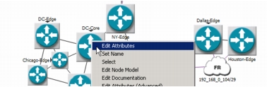
Select DC-Core and select Edit Attributes from the drop-down menu. This displays the attributes for DC-Core.
Figure 7: Selecting Edit Attributes for DC-Core
Result: The Attributes dialog box for DC-Core appears.
-
Expand the IP attribute group.
-
Click in the Value column for IP Routing Parameters and select Edit….
Result: The IP Routing Parameters table appears.
-
Click in the Value column for Interface Information.
Result: The Interface Information table appears.
-
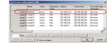
Find the row for ATM1/0.
Figure 8: Interface Information
-
Note that the interface ATM1/0 has an IP address of 192.168.0.114 and a subnet mask of 255.255.255.248.
-
Click Cancel on each open dialog box to close.
-
Right-click on DC-Core and choose Post Import Operations > View Collected Output File from the drop-down menu.
Result: The router configuration file appears.
-
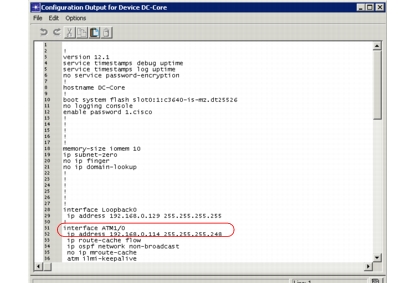
Scroll down to lines 31-32.
-
Note that the name, IP address, and subnet mask in this file match what appears in the Interface Information table.
Figure 9: Router Configuration File
-
Choose File > Close for the router configuration file.
Result: The dialog box that displayed the router file closes.
Importing Traffic
Now that you have imported the topology, you can add traffic to the network by importing a traffic file. When your network has traffic, you can use other features to get an idea of how well this baseline OSPF network is doing. Specifically, you’ll be able to look at link utilizations to see which links, if any, are overloaded or close to overloaded.
Procedure 10: Importing Traffic
-
Choose Traffic > Import Traffic Flows > From Cisco Netflow…
Result: The Traffic Flows Import dialog box opens with a list of all traffic archives that can be imported.
-
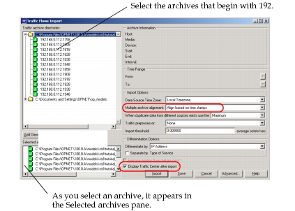
Expand the traffic archive
<reldir>\models\std\tutorial_req\module\traffic.Result: A list of individual traffic files appears.
-
One by one, click on each traffic archive that begins with 192.
Result: As you select an archive, it appears in the Selected archives pane.
Shortcut: You can double-click on the parent folder to select all files within the folder.
Figure 10: Selecting Archives for Import
-
Verify that
- The Display Traffic Center after import checkbox is selected. This will open the Traffic Center dialog box.
- Multiple archive alignment is set to Align based on time stamps.
-
Click Import to start importing traffic into the network.
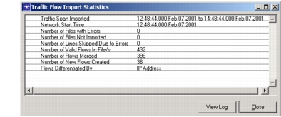
Result: The progress bar shows that traffic files are being imported. When finished, the Traffic Flow Import Statistics dialog box appears.
Figure 11: Traffic Flow Import Statistics
-
Click Close to close the Traffic Flow Import Statistics dialog box.
Result: The Traffic Center dialog box opens.
-
Click Close to close the Traffic Center dialog box.
-
Choose Protocols > IP > Routing > Configure Load Balancing Options…
-
Make sure Packet-Based and All routers are selected, then click OK.
-
Save the completed model by choosing File > Save. Use the default name.
Result: You now have a baseline model fully loaded with traffic.