Productivity Features
This lesson explores Riverbed Modeler productivity features—tools that improve model-building efficiency and usability. This lesson focuses on the following tools:
- Preferences
- Device Creator
- Derived Models
- Logical Object Selection
- Network Browser
- Annotation Palette
This lesson focuses on several special tools, called "Productivity Features," that you can use to improve your model-building efficiency.
Riverbed Modeler has a number of built-in features that have not been used in previous lessons. Although these tools are not essential to model building, they can greatly improve your understanding of models and your modeling efficiency. To familiarize yourself with these tools, you will use each of them to create a network model.
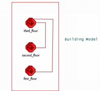
Figure 1: Prod_Features Network Model
Getting Started
For this lesson, you will start with an existing network and use several features to add to and enhance the network.
Procedure 1: Getting Started
-
Choose File > Open… and select Project from the "Files of type" menu (Windows) or the Filters menu (Linux).
-
Navigate to the Prod_Features project, which is located in the following directory:
<reldir>\models\std\tutorial_req\basicResult: The Prod_Features project and scenario open in the Project Editor.
-
Choose File > Save As… and save your project as
<initials>_Prod_Featuresin your default model directory.The Prod_Features project contains a network of three subnets, each representing a floor of a building. The first and second floors contain star-topology 10BaseT Ethernet networks. The third floor, which you will build, is the location of the network's two e-mail servers and a switch that connects the three floors to the outside world. You will use Device Creator to create a special switch and two email servers for the third floor.
In addition, a brief overview of customizing the user interface is provided.
To start, you will change the name of the object palette's model list to reflect your initials.
-
Open the object palette.
Result: The object palette opens with the Prod_Features_Model_List model list active.
-
Right-click on the palette's folder and select Configure in Icon View.
-
Click Save As… in the Configure Palette dialog box.
-
Save the model list as
<initials>_Prod_Featuresin your default model directory. -
Click OK to close the Configure Palette dialog box.
-
Close the object palette.
You can now add or delete models from the model list you created without changing the original model list.
Preferences
Preferences are used to customize Riverbed Modeler.
You can change preferences to customize many aspects of Riverbed Modeler, including the user interface. For example, you can use the following procedure to change the background color of the workspace.
Procedure 2: Changing the Background Color of the Workspace
-
Choose Edit > Preferences.
-
Find the UI > Background Color preference.
To find this preference, type "Background Color" in the "Search for:" field and click Find. This displays all the preferences that contain the string "Background Color." Click on UI in the left-side treeview to limit the list to those preferences that are in the "UI" group.
-
Change the Background Color preference by clicking in its value field and choosing a background color from the color chooser. Then click OK.
-
Click OK to close the Preferences Editor.
Result: The background color has been changed and will take effect after the screen is refreshed (for example, when you open a subnetwork).
Device Creator
Device Creator lets you customize devices and save them.
We will use this feature to create a new 3Com switch for the third floor of your network. You need to modify the standard 3Com switch to a different port configuration.
Procedure 3: Creating a New 3COM Switch
-
Choose Topology > Device Creator > Create Custom Device Model…
-
In the Create Custom Device dialog box, expand Vendor Device.
-
Expand the 3Com folder from the list of available vendors.
-
Select CoreBuilder 3500 from the available devices.
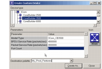
Because you need five 10BaseT ports for the network—one port per server (2), one port for each of the other floors (2), and one port to connect to the outside world (1)—you would probably purchase a 3C35210 card, which has six ports, for the switch. You can specify this in the Port Count setting.
-
Change the value of Port Count to 6.
Figure 2: Create Custom Device Dialog Box
-
You can specify a new palette for the new device. Set the Destination Palette menu to
<initials>_Prod_Features. -
Click Create As…
Result: A naming dialog box appears.
-
In the Model name field, enter
<initials>_Prod_Features_Switch.Result: A message appears when your device is ready.
-
Click OK to close the Status dialog box.
-
Click Close to close the Create Custom Device dialog box.
Derived Models
You can derive customized network models—called derived models—from existing models.
Another way to create a customized model is to derive it from an existing model. This is useful when you have an object with a complex configuration and do not want to configure the object each time you use it. You can create one instance of the object with the necessary configuration and use it wherever necessary. You can also derive models for vendor models that do not come standard with Riverbed Modeler.
Standard models often have a suffix modifier that indicates the level of derivation of the model. An advanced model (_adv suffix) shows all attributes and sets them to their default values. An intermediate model (_int suffix) shows the most important attributes with their most useful values and hides attributes that are unlikely to be changed.
In this section, you will derive a new server from an existing model. The derived server will have over 90 percent of its CPU resources devoted to background processing.
Procedure 4: Deriving a New Server from an Existing Model
-
Open the object palette if it is not already open.
Result: The 3Com CoreBuilder switch that you just created is now listed under
<initials>_Prod_Featurespalette in the 3Com CB 3500 subfolder. -
Select the ethernet_server object and click on the Model Details button.
Result: This opens its node model description, which contains an object description and other important information. You cannot edit the information in this dialog box.
-
Click on the Derive New… button.
Result: The Derive New Model dialog box opens; you can edit the fields in this dialog box.
-
In the CPU Background Utilization row of the Attributes table, select Edit… from the list in the Initial Value column.
-
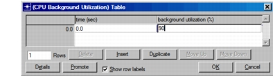
In the CPU Background Utilization table, change the background utilization (%) value from 0.0 to 90.
Figure 3: Changing the Background Utilization Attribute
-
Click OK when finished.
When you create a derived model from another model, you might want to change other aspects of the model, such as the keywords, the icon used to represent the object, and the object description. In this case, you will change the object description only.
-
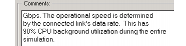
Add a sentence to the end of the first paragraph, noting that this model has 90 percent of its CPU resources in use for the entire simulation.
-
Click on the Save… button when you finish editing the comments.
Result: The Save As… dialog box appears.
-
Navigate to your default model directory, enter the file name
<initials>_Prod_Features_Server, and save the file. -
Close the Edit Derived Model dialog box.
Now that you have created the new derived model, you must add it to the object palette.
-
Open the object palette if it is not already open.
-
Right-click the
<initials>_Prod_Featurespalette folder, and select Configure In Icon View.Result: The object palette switches from the tree view to the icon view.
Result: The Configure Palette dialog box appears.
-
Click the Node Models button.
-
Scroll down until you see the server you just created.
-
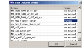
Change the status of the
<initials>_Prod_Features_Servernode model from not included to included, then click OK.Figure 4: Including the Custom Node Model
-
Click OK in the Configure Palette dialog box, then save the palette as
<initials>_Prod_Features. Click OK when you are asked to confirm the overwrite.Result: The derived model
<initials>_Prod_Features_Serverappears in the object palette.Now you can create the third floor subnet, which contains two e-mail servers and the derived 3Com switch. This switch connects to the switches on the other two floors.
-
Double-click to enter the third_floor subnet.
-
Switch object palette view to the treeview, and drag two
<initials>_Prod_Features_Serversfrom the object palette to the left side of the workspace. -
Now you will add the
<initials>_Prod_Features_switchto the model.-
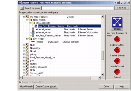
19.1 Expand the 3Com CB 3500 subfolder to display the models in this group (in this case there is only one model in the group).
Figure 5: Object Palette for 3Com CB 3500 Group
-
19.2 Place an
<initials>_Prod_Features_switchto the right of the servers.
-
-
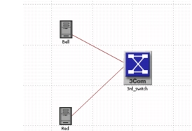
Connect the two servers to the switch using 10BaseT links.
-
Using the Set Name item from the Object pop-up menu, name one server Bell, the other server Red, and the switch 3rd_switch.
Next, we will connect the first and second floors to the third floor.
-
Return to the parent subnet by using the Go to Parent Subnet command in the Workspace pop-up menu or by clicking on the toolbar button.
-
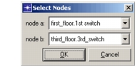
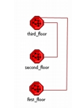
Connect the first_floor subnet to the third_floor subnet with a 10BaseT link. When prompted to select the nodes to connect, select first_floor.1st switch and third_floor.3rd_switch. Click OK.
Figure 6: Select Nodes Dialog Box
-
Connect the second_floor subnet to the third_floor subnet with a 10BaseT link. Select the second_floor.2nd switch and the third_floor.3rd_switch. Click OK.
-
Right-click to turn off link creation.
-
Click in the workspace to unselect all objects.
-
Save the project.
-
Close the object palette.
At this point, your network should be fully functional. However, because this lesson is about productivity tools, we will not run any simulations using the network.
Logical Object Selection
Instead of selecting objects individually, you can use Logical Object Selection to select objects with similar attributes or associations.
Now that you have created the servers for the network, you should check to make sure that all of the workstation nodes are configured correctly, especially because you don't know how the original model developer set the attributes. Because there are workstations in two different subnets of this model, selecting the nodes one-by-one would be tedious and time-consuming. Instead, you can use Logical Object Selection to select all the workstations at the same time.
Procedure 5: Selecting Objects in the Network
-
Choose Edit > Select Objects…
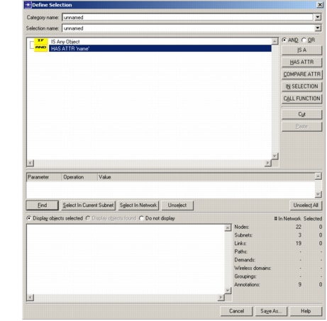
Result: The Define Selection dialog box opens.
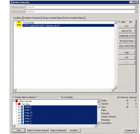
Figure 7: Define Selection Dialog Box
-
Right-click on IS Any Object, and select Node Types > Any Node.
-
Right-click on Has ATTR name, and select Choose Attribute.
-
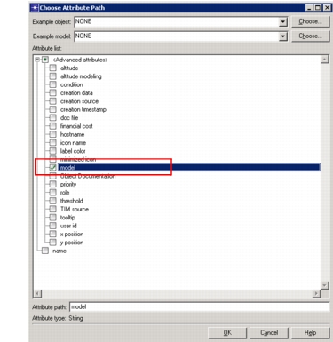
In the Choose Attribute Path dialog, expand the
<Advanced attributes>element, and select the model attribute. Then click OK to close this dialog.Figure 8: Logical Object Selection Dialog Box
-
Right-click on Has ATTR model, and select Define Comparison…
-
In the resulting Attribute Comparison dialog, choose Matches string (MATCHES) in the pull-down menu. Enter ethernet_wkstn in the corresponding field. Click OK to close this dialog.
Figure 9: String Attribute Value Dialog

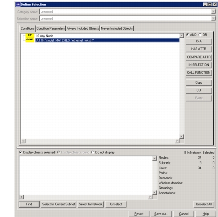
Note that the specification is now as follows:
Figure 10: Define Selection Dialog
-
Click the Select in Network button.
The objects that match the above criteria are now listed in the bottom treeview, and are also selected in the network.
Figure 11: Define Selection Search Results
Now that you have selected all the necessary nodes, set their attributes so that 75% of every workstation's CPU is "background-utilized" during a simulation.
-
Right-click on any of the selected nodes in the treeview, and choose Edit Attributes.
-
Expand the CPU compound attribute by clicking on the "+", then change the value of CPU Background Utilization to Edit…
-
In the CPU Background Utilization table, change the background utilization (%) attribute to 75 and leave the time (sec) attribute at 0.0. Click OK.
-
Select the Apply to selected objects checkbox to ensure that the changes you made are propagated to the other selected workstations.
-
Click OK.
(A message might appear warning you that attribute changes to multiple objects cannot be reverted using the Undo command. Because you are sure you want to make these changes, click Yes to accept them.)
You can look at the background utilization attribute of a workstation in the other subnet to verify that it has been changed.
-
In the Define Selection dialog, click the Save As… button.
-
Enter General for the Category name, and ethernet_wkstn_nodes in the Selection name field. Click OK.
Figure 12: Choose Named Selection Dialog
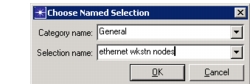
The selection criteria are now saved and can be reused in later sessions.
-
Click Cancel to close the Define Selection dialog.
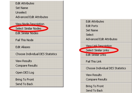
Another way to select objects in the network is with the Select Similar Nodes/Select Similar Links option on the Object pop-up menu. This enables you to select every node or link object in the network whose model attribute is the same as the original object. This function is not available on subnet objects.
Figure 13: Select Similar Nodes/Links Option on Object Pop-Up Menu
Network Browser
The Network Browser uses a treeview to organize and display objects in the network. The browser view and the topology view give different views of the same network. However, the treeview can make it easier to find and edit objects, especially in large networks.
In addition to providing an overview of the network with two views, you can use the Network Browser to traverse the network quickly.
Procedure 6: Using the Network Browser
-
Choose View > Show Network Browser.
Result: The browser opens. There are now two different views of the network objects: a treeview on the left side of the window and a network topology view on the right side of the window.
-
In the treeview, expand the first_floor subnet to view a list of its contents.
-
Click on 1st switch.
Result: 1st switch becomes highlighted in the treeview and in the network topology view.
-
Right-click the 1st switch object (in the treeview or in the network topology view) and select Edit Attributes (Advanced) from the pop-up menu.
-
Click the model attribute to bring up a list of available node models. If a dialog appears asking you to confirm this operation, click Yes. Select
<initials>_Prod_Features_Switchin the list, then click OK.Result: This replaces the existing switch with the derived 3Com switch you created with Device Creator.
-
Collapse the first_floor subnet, then repeat this procedure for the switch on the second_floor subnet.
-
Choose View > Show Network Browser again to close the Network Browser.
Annotation Palette
You can add graphic or text annotations to a network model to improve its readability and understandability. Annotation objects do not affect the functionality of the network model.
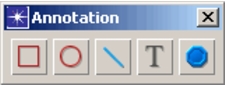
The Annotation tool lets you add text, arrows, and other objects to your model to improve readability or to call attention to important features. In this section, you will use the Annotation tool to clarify several points in the building model. Annotation objects do not affect the functionality of a network model.
Figure 14: Annotation Palette
Procedure 7: Annotating Models
-
Choose Topology > Open Annotation Palette.
Result: The annotation palette opens in the workspace.
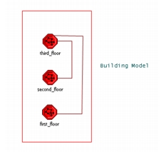
Use the annotation tool to show that each subnet represents a floor within a building:
-
Traverse the network until the first-, second-, and third-floor networks appear as icons (as shown).
Figure 15: Network Model with Annotations
-
Click on the rectangle button in the annotation palette, then draw a rectangle around the three subnets. Right-click to stop drawing, when finished.
-
Click on the text button in the palette and type the annotation "Building Model" in the text edit pad, then choose File > Commit from the text edit pad's menu.
-
Specify the location for the text annotation by dragging a box to the right of the rectangle you drew in step 2. Right-click to stop placing text.
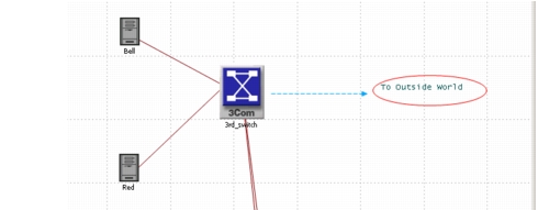
You can also annotate some objects on the third floor to make that part of the model more understandable. Links indicate that the 3rd floor switch is connected to the outside world, but you can add an annotation to make the concept more explicit.
-
Double-click on the third_floor subnet.
-
Add an arrow:
- 7.1 Click the line button in the palette, then draw a line extending to the right from the switch (left-click at the start point, drag the mouse to draw the line, double-click to end the line at the desired point, then right-click to end line drawing).
- 7.2 Right-click on the line and select Edit Attributes.
- 7.3 Change the line style attribute to dashed.
- 7.4 Change the head arrow attribute to yes and click OK.
-
Add the text "To Outside World" to the right of the arrow:
-
8.1 Click on the text tool and type the text in the text edit pad.
-
8.2 Select File > Commit.
-
8.3 Drag the cursor to place the text in the workspace. (Right-click to stop placing text.)
-
8.4 Draw an ellipse around the text.
The third floor subnet should now look like this:
Figure 16: Third Floor Subnet with Annotations
You can add more annotations to the network model if you want. You can also change the color of any annotation object by changing its color attribute. To hide all annotations, choose View > Annotations > Show in Subnet.
When you finish adding annotations to your model, save it.
-
Congratulations! You have completed the core tutorial lessons. Now you can build your own network model, collect statistics, run a simulation, and analyze the results.
You can now proceed with more advanced topics. Return to the main tutorial menu and choose the desired tutorial from the list of available lessons.
If you have questions about certain aspects of Riverbed Modeler, see Help > Product Documentation or visit the Riverbed Support website by choosing Help > Web - Support Center.
Good luck model building!