Packet Switching II
This tutorial assumes that you completed the Packet Switching I tutorial.
In Packet Switching I, you created a simple packet switching network with a hub and four peripheral nodes.
After running the simulation, you discovered that packets went across the network with or without queuing delays, depending on the packet generation rate.
In this lesson, you will see how adding a second network affects the end-to-end delays of packets in the network.
Figure 1: The Expanded Network
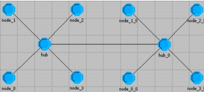
Additionally, you will accomplish the following goals:
- Learn about logical associations in node models
- Redesign the hub model to handle an additional subnet
Getting Started
Begin by opening the project that you created in the Packet Switching I lesson.
Procedure 1: Opening the Project
- Close any editors you still have open from the last lesson.
- Choose File > Open… and verify that the “Files of type:” menu (Windows) or Filters menu (Linux) is set to Project.
- If the displayed directory is not your active working directory (typically <username>/op_models), then navigate to it.
- Choose <initials>_pksw_net and click Open.
- Select Scenarios > Duplicate Scenario… and name the new scenario dual_subnet.
Enhancing the Node Model
To accommodate more connections, the hub node model must have an additional point-to-point transmitter and receiver.
Because the expanded network will connect through the hub, you must add a transmitter/receiver pair to the hub node model.
Adding the Transmitter/Receiver Pair
To add a transmitter/receiver pair, perform the following procedure.
Procedure 2: Adding a Transmitter/Receiver Pair
-
Double-click on the hub node in the Project Editor to open the associated node model in the Node Editor.
-
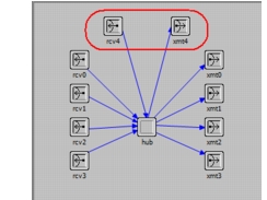
Add a point-to-point transmitter and receiver, as shown in the following figure.
Figure 2: Transmitter and Receiver Added to the Hub Node
-
Set the name attributes to rcv4 and xmt4.
-
Connect the new modules to the hub with packet streams.
-
Right-click on the packet stream from the hub to xmt4 and select Edit Attributes. Note that the src stream is [4], which means that in the process model, the processor should send packets to the transmitter over stream 4.
-
Close the Attributes dialog box.
Setting the Channel Data Rate and Packet Formats
Set the channel data rate and supported packet formats for both new modules, as described in the following procedure.
Procedure 3: Setting the Channel Data Rate and Packet Formats
- Select the new transmitter.
- Right-click on the transmitter and select Edit Attributes.
- Click on the value of the channel attribute.
- Change the data rate to 9600.
- Support the <initials>_pksw_format format.
- 5.1 Click on the value of the packet formats attribute.
- 5.2 Click on both checkboxes to turn off Support all packet formats and Support unformatted packets.
- 5.3 Click on the Status field for <initials>_pksw_format.
- 5.4 Close the Select Supported Packet Formats dialog box.
- 5.5 Close the (channel) Table dialog box.
- Click OK to close the Attributes dialog box.
- Repeat steps 2 through 6 for the receiver module.
Associating Transmitters and Receivers
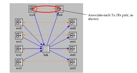
To ensure the correct transmitter/receiver pairs are used when connecting links to nodes at the network level, you can logically associate pairs of transmitters and receivers.
Procedure 4: Associating Transmitters and Receivers
-
Click the Create Logical Tx/Rx Association tool button.

-
Connect the modules, as shown in the following figure.
-
When finished, save the node model and close the Node Editor.
Adding a New Subnet
Now that an extra transmitter/receiver pair is available, the network model can be expanded to connect an additional subnet using point-to-point links.
Adding the Second Subnet
To add a second subnet to the existing network, you can copy the original network and connect the two.
Procedure 5: Adding the Second Subnet
-
If the <initials>_pksw_net project is not already open, open it.
-
Click on the Go to Parent Subnetwork tool button.

-
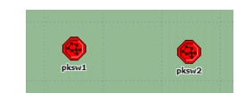
Left-click on the subnet to select it, select Edit > Copy, then Edit > Paste.
-
Position the cursor to the right of the existing subnet and left-click to place the second subnet.
-
Open the <initials>_pksw_palette object palette.
-
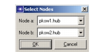
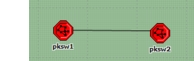
Select the <initials>_pksw_link link model in the <initials>_pksw_palette object palette and connect the two subnets. Click OK in the Select Nodes dialog box.
Adding a User ID Attribute
You also need to add a user id attribute so each subnet can be uniquely identified when routing packets.
Procedure 6: Adding a User ID Attribute
-
Right-click on the pksw1 subnet and choose Edit Attributes from the pop-up menu.
-
Change the user id attribute to 1, then click OK.
-
Right-click on the pksw2 subnet and choose Edit Attributes from the pop-up menu.
-
Change the user id attribute to 2, then click OK to close the dialog box.
Result: The user IDs are assigned to both subnets.
-
Save the project. (Do not close the Project Editor.)
Redefining the Packet Format
There are several ways to deal with the problem of node addressing in different subnets. Adding a packet field that identifies the subnet of the destination node is an easy method.
Procedure 7: Redefining the Packet Format
-
Choose File > Open… and change the “Files of type” menu (Windows) or Filters menu (Linux) to Packet Format. Select the <initials>_pksw_format and click Open.
-
Click on the Create New Field tool button, then place the new field directly beneath the dest_address field.

-
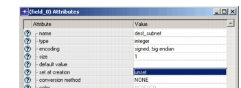
Right-click on the new field and select Edit Attributes, then change the attributes as follows:
- name = dest_subnet
- size = 1 (We only need 1 bit to choose between the two subnets.)
- set at creation = unset
-
Click OK when you are finished to close the dialog box.
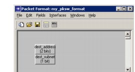
Result: The name and size of the packet field are displayed in the field.
-
Save the packet format and close the Packet Format Editor.
Modifying the Process Model
Before the new network configuration will work, the hub and peripheral node process models must be modified to handle the routing of packets between the two subnets.
Peripheral nodes must assign a destination subnet and destination node address. The subnet address will be either 1 or 2 (these values correspond to a subnet user id attribute). A new line of code in the xmt transition executive will assign a destination subnet randomly.
Modifying the Node Process Model
Procedure 8: Modifying the Node Process Model
-
Open the <initials>_pksw_nd_proc model in the Process Editor.
-
Open the Function Block and add the line of code marked in bold text to the xmt() function:
. . . pkptr = op_pk_get (SRC_IN_STRM); op_pk_nfd_set_int32 (pkptr, "dest_subnet", (int)op_dist_uniform (2.0) + 1); op_pk_nfd_set_int32 (pkptr, "dest_address", (int)op_dist_outcome (address_dist)); op_pk_send (pkptr, XMT_OUT_STRM); FOUT; } -
The dest_subnet field in the packet format has been defined as a 1-bit field. It is going to store the user ID of the destination subnet, i.e. a value of 1 or 2. In a real packet, storing a value of ‘2’ would need more than 1 bit, but in the simulated space, we are just using two arbitrary values that are using just 1 bit of packet space, regardless of their actual binary representation.
-
Select File > Save from the Function Block menu.
-
Compile the process model. You do not need to save the model because it is saved before the compilation.
Modifying the Hub Process Model
With the addition of the second subnet, the hub node process model must now also determine which subnet a packet belongs in and route packets accordingly. An initial state must be added in which the process model determines its surrounding subnet.
Procedure 9: Modifying the Hub Process Model
-
Open the <initials>_pksw_hub_proc model in the Process Editor.
-
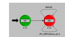
Add a new state to the left of the idle state. Make it an initial state by selecting it and clicking the Set Initial State tool button.

-
Change the name attribute to init and change the status attribute to forced.
-
Create an unconditional transition from the init state to the idle state, as shown above.
The next steps will modify the code in the process model.
-
Open the Header Block and add the line of code marked in bold text:
#define PK_ARRVL (op_intrpt_type () == OPC_INTRPT_STRM)
#define OTHER_SUBNET_STRM 4
The OTHER_SUBNET_STRM symbolic constant refers to the stream attached to the newly created transmitter linked to the other subnet. This is the same as the src stream index value of the packet stream from the hub to xmt4.
-
Close the Header Block and save your changes.
-
Open the state variable block and add the variable subnet_id of type int.
-
Open the init state's Enter Executives and add the following lines of code:
Objid parent_subnet = op_topo_parent (op_topo_parent(op_id_self ()));
op_ima_obj_attr_get_int32 (parent_subnet, "user id", &subnet_id);
The first statement determines the object identifier of the parent subnet using chained calls to the op_topo_parent() procedure.
The second statement uses this value as an argument to the op_ima_obj_attr_get_int32() procedure to obtain the user id attribute of the subnet.
-
Close the Enter Executives and save your changes.
-
Open the Function Block and add the new lines of code marked in bold text to the route_pk() function:
int dest_address;
int dest_subnet;
Packet *pkptr;
FIN (route_pk());
pkptr = op_pk_get (op_intrpt_strm ());
op_pk_nfd_get_int32 (pkptr, "dest_subnet", &dest_subnet);
if (dest_subnet == subnet_id)
   {
   op_pk_nfd_get_int32 (pkptr, "dest_address",
      &dest_address);
   op_pk_send (pkptr, dest_address);
   }
else
   op_pk_send (pkptr, OTHER_SUBNET_STRM);
The modified route_pk() function sends the packet to a local node if the destination subnet value matches the subnet_id obtained in the init state. Otherwise, the packet is sent to the other subnet. 11. Select File > Save from the Function Block menu. 12. Compile the process model, then close the two open Process Editors.
Running the Simulation
Now that all the enhancements to the model are complete, you can run the simulation.
Procedure 10: Running the Simulation
-
In the <intials>_pksw_net Project Editor, select DES > Configure/Run Discrete Event Simulation…
**Note—**If the Configure/Run Discrete Event Simulation dialog box is in Simple view (without a treeview in the left pane), click the Detailed button in the lower-left corner.
-
Click Common in the treeview and change the Simulation set name to <initials>_pksw_out80 (in the right panel).
-
Verify that Duration is set to 1000 seconds.
-
Select and expand the Inputs node, then click on Object Attributes.
-
Delete the pksw1.*.source interarrival time attribute, as follows:
- 5.1 Click the attribute name in the Attribute column to select the attribute.
- 5.2 Click the Delete button.
-
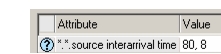
Add *.*.source interarrival time.
-
In the Simulation Set dialog box, set the value for *.*.source interarrival time to 80, 8 using the Enter Multiple Values... button.
-
Click Run to save and execute the new settings. The simulation runs should take a few seconds to run.
Note: If your computer has multiple cores, select consecutive execution of the two simulation runs.
-
When the simulation completes, close the DES Execution Manager dialog box. If you had problems, see "Troubleshooting Tutorials".
Viewing Results
You can now determine how the addition of a second subnet affects the simulation results by reviewing the graph of ETE delay.
Procedure 11: Viewing Results
-
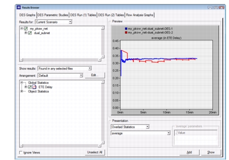
Right-click in the workspace and select View Results.
-
Select the Global Statistics > ETE Delay global statistic.
-
Make sure the graph is set to Overlaid Statistics and change the graph type to average.
-
Click Show.
Result: The graph opens in a new window.
ETE Delay should resemble the following graph. Your results may differ somewhat because of the position of the nodes in your model.
Figure 3: ETE Delay Graph
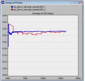
Notice that both simulations appear to settle down after initial spikes. Further, ETE Delay is lower for the first simulation, which is experiencing less traffic. These results seem reasonable.
You might also want to look at other graphs, such as the time average end-to-end delay. When you are finished with this tutorial, close all open editors.
Return to the list of tutorials in the Contents pane and choose CSMA/CD.