Introduction to SITL
This tutorial provides a quick introduction to System-in-the-Loop (SITL) functionality, which allows physical hardware and a simulation to interact as a unified system. This tutorial demonstrates how you can use SITL to do the following:
- Allow physical hardware to interact with a simulation
- Allow multiple physical networks to communicate through a simulation
After finishing this tutorial, you will know how to use Riverbed Modeler and SITL to incorporate physical hardware in a simulation.
Before You Begin
To do this tutorial, you should:
- Know how to use Riverbed Modeler to build network models and run simulations
- Know how to configure Ethernet interfaces and firewalls on your computer
If you are new to Riverbed Modeler, we suggest that you do one or more basic tutorials (such as “Small Internetworks”) before doing this one.
You will need the following items to complete this tutorial:
-
Riverbed Modeler (Release 14.5 or later)
-
SITL license
-
A computer on which to run the software. This computer needs one or more Ethernet interfaces:
- One dedicated interface is needed for the real–sim scenario
- A second dedicated interface is needed for the real–sim–real scenario
- A third interface might be needed to let Riverbed Modeler contact an Riverbed license server (not needed if a license server is running on the local computer or if Riverbed Modeler is running in Standalone license mode)
Note: Each network interface card (NIC) used for a SITL interface must be compatible with the Pcap library that SITL uses to capture and send packets. You can check for supported cards at the website for the Pcap library used by SITL: Winpcap on Windows (www.winpcap.com) and libpcap on Linux (www.tcpdump.org). (SITL prints the Pcap library version being used at the beginning of each simulation.)
-
One or two additional computers to represent the physical hardware in the simulations
Tasklist
The tasks you will perform in this tutorial comprise the following procedures:
- Task 1—Preparing the Simulation Environment
- Task 2—Creating a Real–Sim Scenario
- Task 3—Creating a Real–Sim–Real Scenario
Preparing the Simulation Environment
In this task, you will set up Modeler and the computers to be used so that they are ready to run a SITL simulation.
Prepare the Hardware
Procedure 1: Preparing the Hardware
-
Select two, three, or four computers to use, as follows:
Figure 1: Hardware for SITL Simulation
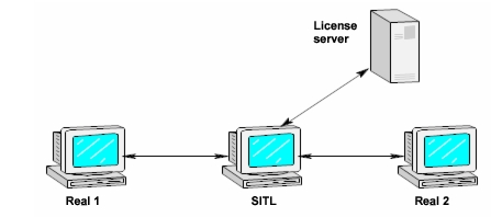
- Real1—Represents a physical network or piece of hardware. Required.
- SITL—Runs the Modeler and SITL software. Required.
- Real2—Represents a second physical network or piece of hardware. Required only for the Real–Sim–Real scenario.
- License server—Required only if Modeler needs a remote license server. (We recommend using a local license server or running Riverbed Modeler in Standalone license mode.)
Note the following:
- All computers must be able to communicate with each other as indicated by the links in the preceding figure. The links are Ethernet connections, either direct or through a network.
- The SITL computer must be running a version of Windows or Linux supported by Modeler and SITL. Real1 and Real2 can be running any operating system.
-
Set up the Ethernet interfaces on the SITL computer.
- 2.1 At a minimum, set the IP address, mask, and gateway for each SITL interface. Each IP address must be unique on the connected network. The mask and gateway should be appropriate for connection to the physical hardware.
- 2.2 If the SITL computer is running Windows, disable Netbios over TCP/IP and all items on the connection except “Internet Protocol (TCP/IP)”.
-
Set up a firewall on the SITL computer for the interfaces that are going to be used in the SITL simulation. The firewall should not allow any exceptions, so as to prevent the operating system from interfering with SITL.
On Windows, you can use the built-in firewall or other firewalls installed on your system. Some third-party firewalls (such as ZoneAlarm) interfere with Pcap, however; if you have one of those, you will have to disable it and use the Windows firewall instead.
Note—Do not put a firewall on the interface to a remote license server.
Prepare the Modeler Software
SITL models are not included in the default repository, so you must disable the use of repositories. This will cause all models to be rebuilt the first time you run a simulation.
Procedure 2: Preparing the Riverbed Modeler Software
- Start Modeler.
- Choose Edit > Preferences.
- Locate the Network Simulation Repositories preference and delete the stdmod entry.
- Close the Preferences Editor.
Creating a Real–Sim Scenario
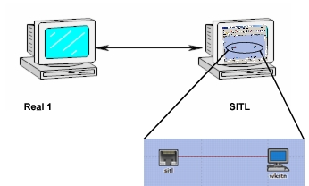
This scenario models communications between two computers. One computer is the physical computer Real1. The other computer is a workstation modeled in a simulation running on the SITL computer. The simulation will comprise two nodes, one representing the connection to the physical computer and the other being the simulated workstation.
Figure 2: Real–Sim Scenario
Create the Simulated Network
You already have the Real1 and SITL computers connected to each other. Now you’ll create the simulated network that will run on the SITL computer.
Procedure 3: Creating the Simulation Network
-
Create a new project with an empty scenario. In the Startup Wizard:
- 1.1 Name the project SITL_Sample and the scenario real_sim.
- 1.2 Select the Office network scale and use the default size.
- 1.3 Include the ethernet_advanced and SITL model families.
-
Open the Object Palette.
-
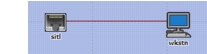
Locate the node model called sitl_virtual_gateway_to_real_world. Drop an instance of this model into the workspace and rename it sitl.
-
Locate the node model called ethernet_wkstn_adv. Drop an instance of this model into the workspace and rename it wkstn.
-
Locate the link model called sitl_virtual_eth_link and use it to connect the sitl gateway node to the wkstn node.
-
5.1 The network model should now resemble the following figure.
-
-
Close the Object Palette.
-
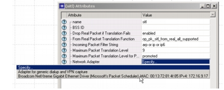
Edit the attributes on the sitl node:
Result: Choose your interface from the Network Adapter pull-down list. This should be the NIC you are using for this simulation.
-
7.1 Set the Incoming Packet Filter String attribute to (arp or icmp) and ether src <SOURCE_MAC_ADDRESS>, where <SOURCE_MAC_ADDRESS> is the MAC address of the interface on Real1 that will be sending packets to SITL.
Note—This is NOT the interface used by the computer running Riverbed Modeler. It resides on the external computer (Real1) that is connected to the SITL interface.
-
7.2 Close the Attributes dialog box.
-
-
Edit the attributes on the wkstn node:
- 8.1 Expand the IP > IP Host Parameters > Interface Information tree and set the Address and Subnet Mask attributes.
- The address must be unique in both the physical and simulated networks (that is, it must be different from the addresses used by the Real1 and SITL computers).
- The address must be in the same subnet as Real1.
- 8.2 Expand the Ethernet > Ethernet Parameters tree and set the Address attribute to 3 (or any single-digit number greater than zero). Some real systems don’t like zero for Ethernet addresses and using a small number will be useful in debugging later on. Like all Ethernet addresses, this should be unique in your system.
- 8.3 Close the Attributes dialog box.
- 8.1 Expand the IP > IP Host Parameters > Interface Information tree and set the Address and Subnet Mask attributes.
Run the Simulation
You now are ready to configure and run the simulation. While the simulation is running, you will test it by pinging the simulated workstation from the external computer (Real1) and observing the response.
Procedure 4: Running the Simulation
-
Open the Configure/Run DES dialog box. If necessary, click the Detailed… button to display the detailed version of the dialog box.
-
Set Simulation Kernel to Development.
You can run SITL simulations in optimized or development mode. We’ll use development here in case you want to examine the internal operation of the simulation.
-
Modeler uses various techniques to make discrete event simulations more efficient (such as pre-assigning routing tables instead of computing them). To prevent these techniques from affecting the simulation, you should disable simulation efficiency for the protocols you will be using with SITL.
-
3.1 In the left pane, expand the tree to Inputs > Global Attributes.
-
3.2 In the Global Attributes pane, expand Simulation Efficiency and disable ARP Sim Efficiency.
**Note—**You can click on the question mark to see a description of this Sim Efficiency technique.
-
3.3 Because we want to coordinate the simulation with real hardware, we must constrain it to run at a real-time speed.
-
3.4 In the left pane, expand the tree to Execution > Advanced > Kernel Preferences.
-
3.5 In the Kernel Preferences pane, set Real-time execution ratio to 1.
-
-
Click Run.
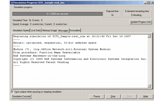
Result: After the model library has been recompiled, the simulation runs. You should get output similar to the following figure.
Figure 3: Simulation Progress Output
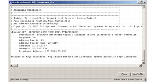
Also, you can look in the Simulation Console to verify that your SITL gateway was successfully matched to the physical interface, as shown in the following figure.
Figure 4: Simulation Console Output
Send Packets Through the Simulation
To demonstrate that the physical hardware and simulated workstation are working together as a single network, ping the simulated workstation from Real1 and view the response.
Procedure 5: Sending Packets Through the Simulation
-
On Real1, enter the ping command:
Windows:
ping -t <wkstn_addr>Linux:
ping <wkstn_addr>where
<wkstn_addr>is the IP address you entered when you configured the wkstn node.This causes ICMP echo request packets to be sent to the simulated workstation via SITL.
Result: Ping replies appear on Real1.
-
To confirm that you are pinging the simulated workstation, pause the simulation for a few seconds, then resume it. Ping responses will stop on Real1 while the simulation is paused.
-
When you are finished looking at the replies, stop the simulation.
If you don’t get any replies to the ping, verify that you have configured everything correctly. If necessary, look at the “Troubleshooting SITL Simulations” section in the SITL documentation. You can observe the packets being sent with a packet capture utility such as Wireshark or by running the simulation with the OPNET Simulation Debugger (ODB) enabled and turning on SITL tracing (with the ltrace sitl command).
Creating a Real–Sim–Real Scenario
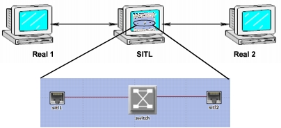
This scenario models communications between two physical nodes by way of a simulated network. The model will comprise three nodes, two representing the physical hardware (with a SITL interface for each) and the third being a simulated network switch.
Figure 5: Real–Sim–Real Scenario
Note: If you do not have two dedicated Ethernet interfaces available in the SITL computer, skip to Summary.
Configure the Simulated Network
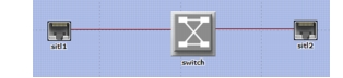
To create the simulated network for this scenario, you’ll duplicate the previous scenario, change the workstation to a switch, and add a second SITL interface to connect to the Real2 computer.
Procedure 6: Configuring the Simulated Network
-
Duplicate the real_sim scenario and name it real_sim_real.
-
Rename the sitl node to sitl1.
If you are using the same computer for Real1 as in the previous scenario, this node needs no further configuration. If you are using a different computer, change the Incoming Packet Filter String attribute to include the MAC address of the new computer.
-
Edit the attributes of the wkstn node:
- Change name to switch.
- Select the Advanced checkbox, then change model to ethernet16_switch_adv.
-
Open the Object Palette.
-
Locate the node model called sitl_virtual_gateway_to_real_world and drop a new instance of this model into the workspace. Name it sitl2.
-
Locate the link model called sitl_virtual_eth_link and use it to connect switch to sitl2.
-
Close the Object Palette.
Result: The network model should now resemble the following figure.
-
Edit the attributes on the sitl2 node:
-
8.1 Choose your interface from the Network Adapter pull-down list. This is the interface on the SITL computer that connects (either directly or through a network) to Real2. Do not use the same interface used by the sitl1 node.
-
8.2 Set the Incoming Packet Filter String attribute to (arp or ip) and ether src <SOURCE_MAC_ADDRESS>, where <SOURCE_MAC_ADDRESS> is the MAC address of the interface on Real2 that will be sending packets to SITL.
Note—This is not the interface used by the computer running Riverbed Modeler. It resides on the external computer (Real2) that is connected to this SITL interface.
-
8.3 Close the attributes dialog box.
-
Connection Summary
On Real1 and Real2, the Ethernet interfaces connected to SITL should have IP addresses in the same network as the two Ethernet interfaces on SITL. On all four interfaces, the gateway should be set to the interface at the other end of the wire. For example:
- Real1 interface connected to SITL interface 1
- IP: 18.0.0.1
- Gateway: 18.0.0.2
- SITL interface 1 connected to Real1
- IP: 18.0.0.2
- Gateway: 18.0.0.1
- SITL interface 2 connected to Real2
- IP: 18.0.0.3
- Gateway: 18.0.0.4
- Real2 interface connected to SITL interface 2
- IP: 18.0.0.4
- Gateway: 18.0.0.3
Run the Simulation
You now are ready to configure and run the simulation. While the simulation is running, you will test it by streaming video through the simulated switch from one external computer to the other.
Procedure 7: Running the Simulation
-
Open the Configure/Run DES dialog box. If necessary, click the Detailed… button to display the detailed version of the dialog box.
-
Set Simulation Kernel to Development.
-
Confirm that the simulation will run at a real-time speed:
- 3.1 In the left pane, expand the tree to Execution > Advanced > Kernel Preferences.
- 3.2 In the Kernel Preferences pane, verify that Real-time execution ratio is set to 1.
-
Click Run.
Result: The simulation runs. You should get output similar to the following figure.
Figure 6: Simulation Progress Output
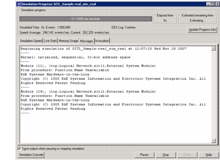
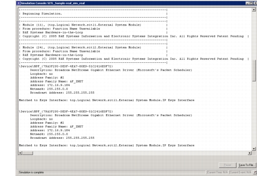
Additionally, you can look in the Simulation Console to verify that both SITL gateways were successfully matched to physical interfaces, as shown in the following figure.
Figure 7: Simulation Console Output
Send Packets Through the Simulation
To demonstrate that the simulated switch is routing traffic between the two physical computers, you can stream video from Real1 to Real2 through the SITL simulation.
Note: Optionally, you can skip the steps in this section and demonstrate connectivity simply by pinging Real2 from Real1 or Real1 from Real2.
To use video streaming, you need applications that can stream and receive video. This tutorial uses VLC media player, a free program available at http://www.videolan.org/. However, you can use any suitable program you have available.
Procedure 8: Sending Packets Through the Simulation
Note: This procedure is based on VLC media player version 1.0.5. If you have a different version, menus and steps might differ, but the general workflow remains the same.
- On computer Real2, install and start VLC media player. We’ll call this instance of the program MP2.
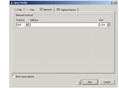
- Configure MP2 to receive and play a video stream by listening on UDP port 1234 (or any other available UDP port).
-
2.1 Choose Media > Open Network Stream…
-
2.2 Select UDP in the Protocol pull-down and set Port to 1234.
Figure 8: VLC Media Player Setup for MP2: Open Network Stream
-
2.3 Click Play.
-
- On computer Real1, install and start another instance of VLC media player (we’ll call this instance MP1).
- Configure MP1 to play a video file (or DVD) and stream the video to computer Real2, using the same UDP port you set up for MP2.
-
4.1 Select the video source:
-
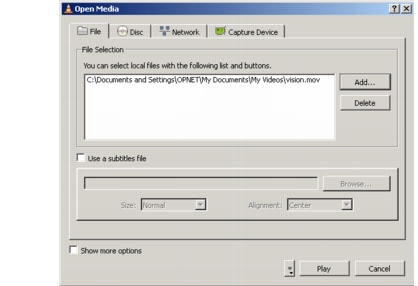
To play a video file, choose Media > Advanced Open File…, click Add…, and select a video file.
Figure 9: VLC Media Player Setup for MP1: Advanced Open File
-
To play video from a DVD, choose File > Open Disc… and select the disk device.
-
-
4.2 From the Select play mode pull-down (next to the Play button), choose Stream (or press Alt-S).
Result: The Stream Output dialog box opens. The Source field displays the file or DVD device you selected in the previous step.
-
4.3 Click Next to move to the Destinations page.
-
4.4 From the New destination pull-down, choose UDP, then click Add.
-
4.5 Set Address to the physical IP address of computer Real2 and Port to 1234.
-
4.6 Click Stream.
Result: After a short delay, you should see the video being played in MP2 on computer Real2.
Note: If you don’t see video, make sure MP1 and MP2 are not paused.
-
- When you are finished with the video, stop MP1 and MP2, then stop the simulation.
Summary
You’ve seen how to use System-in-the-Loop functionality to map physical interfaces to addresses in a simulated network. In this tutorial, you have
- Build and run a SITL system in which physical hardware interacts with a simulation
- Build and run a SITL system that allowed multiple physical networks to communicate through a simulation
For more information about SITL, see the SITL documentation.