OVIS Graphical Decorations
Every graphical decoration exists until it is explicitly destroyed. It has a set of properties that can be modified, resulting in appropriate changes in the 3D display.
2D decorations appear in the 3D Network Visualizer window; their positions in the window are not affected by changes in the viewpoint. By contrast, 3D decorations appear as three-dimensional objects in the network visualization. This means that 3D Network Visualizer shows only those 3D decorations that are within the eyepoint’s line of sight.
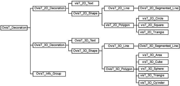
The animation library includes some “parent” decoration types that share information and encompass several of the decorations described in this section. APIs that use the parent decoration types can be used with any of the decorations that fit that type.
Figure 5: Hierarchy of Decoration Types
Creating Decorations
Each decoration type has a creator function. You can create, query, and modify decorations using the procedures described in Decoration Sub-Package.
Decorations have a fixed set of attributes, but each element can have an associated user-defined state. That state is assigned to a decoration using Ovis_Decoration_State_Set() and retrieved using Ovis_Decoration_State_Get().
Ovis Information Layers
Riverbed analysis software uses information layers to provide the ability to show/hide a set of related decorations. This prevents having too many graphical decorations in the animation. Layers can include any number of decorations and other layers. There is a root layer that cannot be destroyed.
Ovis layers are organized beneath a “root” layer which cannot be destroyed. Beneath this is the “Subnet Topology” layer that corresponds to the top-level subnet in the scenario. Beneath this layer are sublayers that correspond to the subnet hierarchy in the scenario. Each layer contains any entities that are mapped to nodes. There is also a “Network Links” layer (at the same level as the “Subnet Topology” layer) that contains any lines that are used to represent simplex or duplex links (as described in Links).
Showing a layer will show its decorations and child layers (recursively showing.) Hiding a layer will hide its decorations and child layers (recursively hiding).
A layer is created using Ovis_Layer_Create() and destroyed with Ovis_Layer_Destroy(). The root layer is accessed using Ovis_Root_Layer_Get(). You can access the layer of a site using Ovis_Site_Layer_Get(). Ovis_Layer_Id_Get() returns the unique creation ID of the specified layer.
You can specify a parent layer when creating a new layer. You can also dynamically add or remove a layer as a child of another with Ovis_Layer_Parent_Set(). Ovis_Layer_Parent_Get() returns the parent of a layer. You can evaluate child layers using Ovis_Layer_Child_Layer_Count() and Ovis_Layer_Child_Layer_Nth().
Similarly, you can specify an initial layer when creating a decoration, and dynamically add decorations to, or remove them from, layers using Ovis_Layer_Decoration_Add() or Ovis_Layer_Decoration_Remove().
The decorations associated with a given layer are accessed using Ovis_Layer_Child_Decoration_Count() and Ovis_Layer_Child_Decoration_Nth().
The same decoration can belong to multiple layers, which can be retrieved with Ovis_Decoration_Parent_Layer_Count() and Ovis_Decoration_Parent_Layer_Nth().
A layer and its associated children (other layers or decorations) are shown with Ovis_Layer_Show() and hidden with Ovis_Layer_Hide().
Positioning
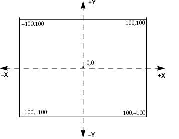
Decorations come in 2D and 3D versions. 2D decorations are placed in the viewer window using integer positions between –100 and 100 in X and Y coordinates, where (0,0) is the center of the window and (100,100) is the top-right corner (see Figure 6). Their positions do not change when the viewpoint is moved around. 3D decorations are placed in the 3D scene and move with the viewpoint, possibly being clipped off.
Figure 6: Viewer Coordinate System
There are several ways of specifying 3D coordinates for decorations:
- Absolute positioning:
- Geocentric (X,Y,Z) coordinates
- Geodetic (latitude, longitude, altitude) coordinates
- Relative positioning: Referencing the current position of another object (mapped entity, 3D line, etc.). In this case, changes in the other object’s position will ensure that anything using that position is moved as well. So for example a line connected to two objects will stretch appropriately as these objects move. In the case of a line reference object, the locator also includes an integer percentage indicating the attachment point along the line, between the start (0%) and end (100%).
We use a common locator to represent the various 3D forms so that the positioning APIs are simplified. The locator is as follows:
typedef struct
   {
   int x, y;
   } OvisT_2D_Position;

typedef struct
   {
   double x_offset, y_offset;
   } OvisT_2D_Corner;

typedef enum
   {
   OvisC_3D_Geocentric,
   OvisC_3D_Geodetic,
   OvisC_3D_Entity,
   OvisC_3D_Decoration
   } OvisT_3D_Position_Type;

typedef struct
   {
   double x, y, z;
   } OvisT_3D_Geocentric_Pos;

typedef struct
   {
   double lat, lon, alt;
   } OvisT_3D_Geodetic_Pos;

typedef struct
   {
   OvisT_Decoration  id;
   unsigned char	percent; /* 0 -100, along line/cylinder */
   } OvisT_3D_Decoration_Pos;

typedef struct
   {
   OvisT_3D_Position_Type	type;
   enum pos
      {
      OvisT_3D_Geocentric_Pos xyz;
      OvisT_3D_Geodetic_Pos lla;
      OvisT_Entity ent;
      OvisT_Decoration_Pos dec;
      }
   } OvisT_3D_Position;
You can manipulate these data structures directly, or you can use the following procedures to ensure that all necessary fields are set correctly:
- Ovis_3D_Position_Decoration_Set()
- Ovis_3D_Position_Entity_Set()
- Ovis_3D_Position_Geocentric_Set()
- Ovis_3D_Position_Geodetic_Set()
Updating Decorations
An element is created with default attribute values. Some APIs apply to all object types; others are specific to a specific type (the type appears in the function name) and will cause warnings if used with an incorrect type.
You can query and modify decorations using the procedures described in Decoration Sub-Package.
Node Mapping
Each node model can have its own mapping library, with appropriate callbacks. These are not directly invoked by the Ovis package. Instead the callbacks in the network mapping library are responsible for checking for any node callbacks and invoking them appropriately.
To specify a mapping attribute on a node model for the provided opnet_default_3dnv_mapping library, you need to create a string attribute named “3DNV Node Mapping”.
The mapping library referenced by that attribute should include a mapping node callback as defined in OvisT_Mapping_Node_Proc.
Enabling a 3D Network Visualization
The visualization of a network model is enabled when either of the following events occurs:
- The user chooses Topology > 3DNV > Display 3D Network View in Project Editor.
- The user loads a network model while 3D Network Visualizer has been enabled in the simulation (DES).
The first time you enable 3D Network Visualizer, the Riverbed application creates an appropriate HLA federation and either optionally launches 3D Network Visualizer (same machine) or lets the user know how to launch it (same or different machine).
When you enable 3D Network Visualizer for a given network model, two callbacks of the mapping library are invoked:
- The “load” callback in invoked (signature defined as OvisT_Mapping_Load_Proc) to perform the initialization. The callback can create a global state that will be passed in subsequent invocations of the other mapping callbacks.
- The “enable” callback (OvisT_Mapping_Enable_Proc) is invoked with the ID of the top subnet. The model code is responsible for
- Potentially creating an appropriate OvisT_Entity for the subnet itself
- Traversing the subnet's topology and checking the sites (nodes and subnets) For each node, call Ovis_Node_Mapping_Get(). This will check if the node has a node-level mapping library and return its 'enable' callback, which the caller should invoke. For each subnet, the mapping is free to skip it, just map it to some aggregate, or recursively process the subnet.
If the callback returns failure, the 3D visualization is not enabled for the subnet.
The mapping library can check if a given site should be shown based on the current user settings (views, layers, show/hide sites, probes, etc.) and avoid creating Ovis entities for sites that should not be visible.
Once the callback returns, the Ovis library will instantiate all the appropriate RTI objects.
Disabling a 3D Network Visualization
A 3D network visualization is disabled for a given network model when either of the following events occurs:
- The user chooses Topology > 3DNV > Display 3D Network View in Project Editor.
- The user closes a network model while 3D Network Visualizer has been enabled at the Project Editor level (GUI) or the simulation terminates (DES).
When this happens, the “disable” network mapping callback (OvisT_Mapping_Disable_Proc) is invoked with the ID of the top subnet, and the state from the “load” callback. The model code can take advantage of this to perform appropriate cleanup. There is no need for the mapping library to actually destroy Ovis entities as these will be automatically destroyed by the Ovis package once the “disable” callback returns.
Creating/Destroying a Site
Creating a new site invokes the “enable” callback with the new site’s handle and the optional state. Destroying an existing site invokes the “disable” callback with the site’s handle and the optional state. Note that the “disable” callback is NOT invoked when an OvisT_Entity is explicitly destroyed by user code. Changing the model of a mapped node instance is the same as destroying that node and creating a new node.
Discovering RTI Objects
If the Riverbed application is part of a larger HLA federation, it is possible to have RTI objects created by other federates. These objects are going to be discovered by both 3D Network Visualizer and the application. 3D Network Visualizer will display these objects if they correspond to things that can be displayed. Additionally, it is important for the Riverbed application to map these discovered objects to ensure a uniform view. Furthermore, it is quite likely that the positions of these discovered objects will be provided by the creator or creators of the objects, with the Riverbed application obtaining position updates through RTI.
Note: This is independent of the optional mapping available in the High-Level Architecture functionality. You can use the 3D Network Visualizer mapping in more general HLA development.
Potential Discovery
If only 3D Network Visualizer is in use, only the Riverbed application can create RTI objects to appear in the 3D display. By itself, 3D Network Visualizer does not create RTI objects. If the High-Level Architecture functionality is in use as well, both the Riverbed application and 3D Network Visualizer belong to a larger federation where other RTI objects are going to be created and some of these objects should be attached to Ovis entities.
Reacting to the Discovery
Upon receiving the first attribute update for a discovered object, the Ovis module will invoke a user-provided mapping callback to evaluate the possibility of a mapping. Two versions are provided: one based on the RTI data structures and one based on the VR-Link versions. These are C++ functions that return an OvisT_Entity * if such a mapping is feasible; otherwise, it returns OVISC_NIL. The system will invoke the VR-Link version, if it is available; otherwise, it invokes the rti version.
Site Motion
The Ovis package uses the ETS infrastructure to register a motion callback for all the sites that have associated OvisT_Entity. When one such site is moved in the GUI (edit attribute, drag, using time motion), the geocentric coordinate of the corresponding RTI objects are updated for the 3D representation.
Similarly, any changes to the position of a DES site that has an associated Ovis entity will result in appropriate RTI updates.
File Representation
Source Code
The mapping file code is in standard .ex.c or .ex.cpp files. The callback function names are defined by the user. The only requirement is that there is a library loading function based on the expected library name with a _init suffix such that Ovis loading library X will look for symbol X_init to obtain callback initializations.
The loading function returns to Ovis a structure containing pointers to the various callbacks. These pointers can be nil. This also includes an optional description string to be presented to user (say once a mapping has been selected).
The follow code represents a skeleton for such a file, which would be used in a library called 'skeleton_mapping.
#include "ovis.h"
static void *
skeleton_mapping_load (EtsT_Model_Handle network_model,
const char * string_arg, OvisT_Compcode * compcode_ptr)
	{
	void * state_ptr;

	FIN (skeleton_mapping_load);

	FRET (state_ptr);
	}

/* unload network model */
static void
skeleton_mapping_unload (void * state_ptr)
	{
	FIN (skeleton_mapping_unload);

	FOUT;
	}


/* enable 3DNV visualization for site ('top' first time, 	*/
/* specific site when creating 								*/
static OvisT_Compcode
skeleton_mapping_enable (EtsT_Obj_Handle obj_handle, void * state_ptr)
	{
	OvisT_Compcode				compcode;

	FIN (skeleton_mapping_enable (obj, state_ptr));

	FRET (compcode);
	}

/* disable 3DNV visualization for site ('top' when turning off entire  	*/
/* visualization, specific site when destroying site) 					*/
static OvisT_Compcode
skeleton_mapping_disable (EtsT_Obj_Handle obj_handle, void * state_ptr)
	{
	OvisT_Compcode	compcode;

	FIN (skeleton_mapping_disable (obj, state_ptr));

	FRET (compcode);
	}

/* A mapped object had some attributes modified */
static void
skeleton_mapping_attribute (EtsT_Obj_Handle obj_handle,
	const char * attr_name, void * state_ptr)
	{
	FIN (skeleton_mapping_attribute);

	FOUT;
	}

/* The library base name is the same as this function without */
/* the _init suffix, i.e., 'skeleton_mapping' */
DLLEXPORT OvisT_Mapping_Init *
skeleton_mapping_init (void)
	{
	static OvisT_Mapping_Init callbacks =
		{
		"Example of mapping library",
		skeleton_mapping_load,
		skeleton_mapping_unload,
		skeleton_mapping_enable,
		skeleton_mapping_disable,
		skeleton_mapping_attribute,
		(OvisT_Mapping_Node_Proc)VOSC_NIL,
#if defined (OPD_DES)
		(OvisT_Mapping_Discover_Proc_Vrlink)VOSC_NIL,
		(OvisT_Mapping_Discover_Proc_Rti)VOSC_NIL
#else
		/* No GUI-specific callbacks */
#endif
		};

	FIN (skeleton_mapping_init);
	FRET (&callbacks);
	}/*
Object / Libraries
When compiling with a specific kernel type, OPD_DES is defined and an appropriate <kernel_type>.ex.o/obj file is generated. This might include some ETS headers, but most of the functionality will be commented out.
A new target type for op_mko—enabled using the -gui command-line argument—compiles with OPD_GUI defined (and OPD_DES undefined), generating gui32.ex.o/obj. This compiles with the expected ETS headers.
op_mkso is extended with a new “nvism” target type (used in conjunction with the -type command-line argument) to generate an nvism.<target_type>.so/dll library based on a set of ex.o/obj files. The GUI version—enabled using the -gui command-line argument—is linked against the ETS and prg libraries. The DES version is linked against the appropriate sim kernel and prg library.
DES Execution Flows
With 3D Network Visualizer enabled, a simulation executes in the cosimulation mode. Various additional actions can occur during the simulation.
- 3D Network Visualizer initialization is performed after the simulation is loaded, but before the first interrupt. When using ODB, this occurs between the first and second prompts. This includes:
- Loading 3D Network Visualizer and the support libraries
- Loading a mapping library, if specified
- Creating initial entities using the mapping library
- If the simulation is part of a larger HLA federation, the Riverbed application might discover new RTI objects and the mapping library involved to optionally associate an Ovis entity with that discovered object
- Animation callbacks can be registered by process modules. These callbacks are involved as communications occur, or as receiver groups are modified.