3D Network Visualization Entities
A network model contains subnets, nodes, links, demands, and paths. All these can appear in a 3D space, but the objects do not necessarily provide all the information needed for 3D visualization. Thus, you must define the additional information needed for each item. That information is used either to generate a 3D representation of the current network model (from the GUI) or during a simulation.
3D Objects in 3D Network Visualizer
3D Network Visualizer uses the RPR-FOM to describe what objects to represent and where to represent them. Each RTI object has an associated type that is mapped to some complex 3D model (tank, plane, etc.) and other attributes that are used to depict the state of the object (position, orientation, movement, damage, etc.)
Active vs. Reactive RTI
Basic 3D Network Visualizer
The basic 3D Network Visualizer has an application process (GUI or DES) generate 3D entities to be rendered by a 3D Network Visualizer process. For this, it is necessary to map from the Riverbed application space to the 3D Network Visualizer space. This means creating appropriate RTI objects based on what is found in the application space and applying the mapping rules.
Advanced 3D Network Visualizer Reactive Mode
In a more advanced mode, where the application and 3D Network Visualizer are part of a larger HLA federation, RTI objects can exist independently of either one. Furthermore, instead of having the Riverbed application systematically create a set of RTI objects for 3D Network Visualizer to render, the application can discover existing objects and match some of these to objects based on the mapping. This is related to the mapping rules of the High-Level Architecture functionality.
Note: External objects are supported only in the discovery of a simulation.
3D Types
VR-Link/RPR-FOM uses the DIS type information, which is a septuplet of numbers used to define the domain, country, etc., for a given item. That type is then related to some 3D model to render. This is also used to define which objects to show for aggregates.
Matching Sites and 3D Network Visualizer Entities
3D Network Visualizer Entities
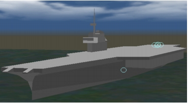
In Figure 2, the aircraft carrier is an aggregate. The various circles indicate individual 3D models that are too small to be visible in this view.
Figure 2: 3D Network Visualizer Entities
Subnets
A subnet is really a container for other things. The matching element in 3D Network Visualizer is called an aggregate, which is shown as a single entity or 3D model.
Table 2: Aggregate Attributes
| Subnet Attribute | Aggregate Property |
|---|---|
| Name | Name |
| Position (geo X/Y/Z) | Position (geo X/Y/Z) |
<need mapping> |
Size (X/Y/Z) |
| Trajectory (mobile subnet) | Orientation (3 axis), Velocity, Acceleration |
| Color (of span) | Color |
<need mapping> |
Type |
<need mapping> |
Force id: Friend/foe/neutral |
Note: You can map a node to an aggregate or a subnet to an entity, as well.
Nodes
A node normally can be mapped to a 3D Network Visualizer entity. While the application only cares about the exact position of the node, 3D Network Visualizer also needs to know the 3D orientation of that node.
When using trajectories, orientation information can be calculated based on a trajectory segment. The only missing part is the roll around the segment axis. For stationary nodes, the orientation simply needs to be set so that the object base is flat on the ground.
Table 3: Entity Attributes
| Node Attribute | Entity Property |
|---|---|
| Name | Name |
| Position (geo X/Y/Z) | Position (geo X/Y/Z) |
| Trajectory (mobile node) Need definition of roll value around segment. |
Orientation, Velocity, Acceleration |
<need mapping> |
Type |
<need mapping> |
Force id: Friend/foe/neutral |
<need mapping> |
Dead Reckoning algorithm |
Links
3D Network Visualizer uses lines to represent simplex and duplex links between mapped sites (nodes or links). The line appearance is based on the “color”, “thickness”, “line style”, and “arrowheads” of the individual link. All links appear in the “Network Links” layer.
Paths/Demands
These do not have an actual match in 3D Network Visualizer, but 3D Network Visualizer has the ability to draw lines between arbitrary points in space or between objects.
3D Positioning
3D Network Visualizer provides the ability to clamp land-based entities to the ground, but flying entities need correct orientation.
Freespace Orientation
One standard scheme is based on three rotations around the object’s local referential. The local referential is set up so that the X axis is tangent to the Earth at the object position, and is in the plane going through the position, the center of the Earth, and the North Pole, the Y axis is on the “right” side of the object while looking down X, and the Z axis goes down from the position to the center of the Earth.
Using that local referential, there are three rotations:
Figure 3: Pitch, Yaw, and Roll
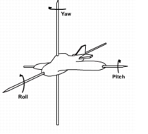
There are three attributes to mobile nodes to represent the pitch, yaw, and roll rotations in degrees.
Trajectory-Based Motion
If a mobile object’s motion is specified using a trajectory (or vector), the pitch and yaw values can either be implicitly defined by the trajectory data or they can be auto-calculated. Only the roll around the trajectory must be explicitly defined.
Trajectory data files can include optional Pitch, Yaw, and Roll values.
The GUI to define trajectory provides an initial checkbox to include roll. Roll is interpolated along a segment based on the initial and ending roll values.
Fixed nodes
Fixed nodes do not have pitch/yaw/roll attributes. They use 0 values for their positioning. Typically, these nodes are going to represent hardware that does not have to face a specific direction.
Ovis Entities
Instead of direct references to ETS or DES sites, the application uses an Ovis entity that refers to a 3D representation of an ETS or DES site.
The object representation is an opaque data structure named OvisT_Entity.
Managing Ovis Entities
Ovis entities are created by user code. The Ovis package will not create Ovis entities automatically, but it can potentially destroy them. The user code that creates these Ovis entities is located in an Ovis mapping library that is associated with a network or a node model or in standard simulation model code (process model, etc.). Ovis invokes appropriate callbacks in the mapping library when 3D Network Visualizer is enabled/disabled, or as individual sites are rendered in 3D or not based on user input (GUI) or model control (DES).
The mapping library provides Ovis with the missing information that cannot be derived from the built-in node attribute, as described previously. The mapping library is primarily responsible for determining which objects should be mapped and how. Riverbed provides one Ovis mapping library (default_3dnv_mapping), which is based on well-defined attributes in a node model.
Entity Groups
Riverbed analysis software uses groups to provide the ability to show/hide a set of related entities. Groups can include any number of entities and other groups. There is a root group that cannot be destroyed. Showing a group will show its entities and child groups (recursively showing.) Hiding a group will hide its entities and child groups (recursively hiding).
A group is created using Ovis_Group_Create() and destroyed with Ovis_Group_Destroy(). The destroy process uses a custom procedure specified with Ovis_Group_Destroy_Proc_Set(). The root group is accessed using Ovis_Root_Group_Get(). Ovis_Group_Id_Get() returns the unique creation ID of the specified group.
You can specify a parent group when creating a new group. You can also dynamically add or remove a group as a child of another with Ovis_Group_Parent_Set(). Ovis_Group_Parent_Get() returns the parent of a group. You can evaluate child groups using Ovis_Group_Child_Group_Count() and Ovis_Group_Child_Group_Nth().
Similarly, you can specify an initial group when creating an entity and dynamically add entities to or remove them from groups using Ovis_Group_Entity_Add() or Ovis_Group_Entity_Remove().
The entities associated with a given group are accessed using Ovis_Group_Child_Entity_Count() and Ovis_Group_Child_Entity_Nth().
The same entity can belong to multiple groups, which can be retrieved with Ovis_Entity_Parent_Group_Count() and Ovis_Entity_Parent_Group_Nth().
A group and its associated children (other groups or entities) are shown with Ovis_Group_Show() and hidden with Ovis_Group_Hide().
Obtaining Ovis Entities
Ovis entities are created (and destroyed) dynamically by model code. Riverbed provides two mapping libraries (ETS and DES) based on the rules defined, but users can create their own mapping libraries.
An Ovis entity always corresponds to a object in the network model, and only one Ovis entity can be associated with a given object. Trying to create a second Ovis entity will return the existing object.
Environment-Agnostic API
You can associate an Ovis entity with an ETS/DES object using Ovis_Entity_Create().
Environment-Specific API
The Ovis library includes two sets of procedures for compiling ETS code and simulation code:
- When compiling ETS code, you can use Ovis_Entity_From_Objhandle_Create() to associate an Ovis entity with an Ets object handle. Ovis_Entity_From_Objhandle_Get() and Ovis_Entity_Objhandle_Get() are available to obtain one item from the other.
- When compiling code for a simulation, you can obtain the same functionality using Ovis_Entity_From_Objid_Create(), Ovis_Entity_From_Objid_Get() and Ovis_Entity_Objid_Get().
For simplicity, the “Objhandle” versions are also provided in the context of the simulation compilation; these macros are used to map EtsT_Obj_Handle IDs to DES object IDs.
Associating RTI Element
In the basic 3D Network Visualizer mode, the application creates all necessary RTI objects. In the advanced mode, some RTI objects are created by other federates and discovered by the Riverbed simulation.
Providing VR-Link/RTI Information
The VR-Link object shown in 3D needs to be dynamically created by the Riverbed application based on information found on the site or through some arbitrary mapping data. This interface is tied to the VR-Link underlying representation, but without explicit references to the VR-Link API to avoid requiring users to have access to the VR-Link development environment (which Riverbed does not provide).
Most of the information necessary to create a VR-Link object is available from the site itself. The user needs to provide the object type, its friend/foe/neutral status, and a dead-reckoning algorithm for moving nodes.
typedef struct
   {
   int kind, domain, country, category, sub_category, specific, extra;
   } OvisT_DIS_Type;

enum OvisT_DIS_Force
   {
   OvisC_DIS_Force_Other  = 0,
   OvisC_DIS_Force_Friendly = 1,
   OvisC_DIS_Force_Opposing = 2,
   OvisC_DIS_Force_Neutral = 3
   };

enum OvisT_DIS_Dead_Reckoning
   {
   OvisC_DIS_DR_Other = 0,
   OvisC_DIS_DR_Static = 1,
   OvisC_DIS_DR_FPW  = 2,
   OvisC_DIS_DR_RPW  = 3,
   OvisC_DIS_DR_RVW  = 4,
   OvisC_DIS_DR_FVW  = 5,
   OvisC_DIS_DR_FPB  = 6,
   OvisC_DIS_DR_RPB  = 7,
   OvisC_DIS_DR_RVB  = 8,
   OvisC_DIS_DR_FVB  = 9,
   OvisC_DIS_DR_Ignored = 10 /* For aggregates */
   };
This information is provided to 3D Network Visualizer using Ovis_Entity_Animation_Set() and can be retrieved using Ovis_Entity_Animation_Get(). You can also clear up any information (thus also destroying the associated 3D entity) using Ovis_Entity_Animation_Disable().
This does not create the corresponding VR-Link/RTI object. It simply provides the necessary information for the Ovis package to create the object later on.
The corresponding VR-Link/RTI object created will be destroyed automatically if the Ovis entity is destroyed or if the representation information is removed from the Ovis entity.
If an RTI object is already defined, providing new DIS values for the Ovis entity will result in the existing RTI object to be destroyed and a new RTI object to be created.
Discovering Objects
This is a DES-only operation. See the DES mapping library section.
Detaching from VR-Link/RTI
User code should not destroy the associated VR-Link /RTI object directly. Instead, the DIS information associated with the Ovis entity is cleared (using Ovis_Entity_Representation_Clear() defined previously). For RTI objects:
- If the RTI object had been created by the Riverbed application, it will be destroyed.
- If the RTI object was discovered by the Riverbed application, it is left as is, but is no longer associated with any Ovis entity.
Access to Underlying RTI & VR-Link Data
For more advanced users who also own licenses to VR-Link or RTI, Riverbed provides APIs that exposes some of the VR-link/RTI information.
If OPD_3DNV_RTI_API is defined, you can use Ovis_Entity_Rti_Object_Get() to retrieve the associated RTI object.
If OPD_3DNV_VRLINK_API is defined, one can use Ovis_Entity_Vrlink_Object_Get() and Ovis_Entity_Vrlink_Publisher_Get() to access the corresponding VR-Link C++ objects.
Freeing Objects
Destroying an Ovis entity with Ovis_Entity_Destroy() will automatically destroy an associated VR-Link object if it had been created by the Riverbed API. Discovered RTI objects are not destroyed.
Accessing Information
Attributes of the mapped node or subnet can be retrieved using the environment-specific mechanism, or using a uniform API that works both in ETS and simulation compilations: Ovis_Entity_Attr_Get_Int32(), Ovis_Entity_Attr_Get_Dbl(), and Ovis_Entity_Attr_Get_Str().
An optional user state pointer can be associated with a mapped object. It will be involved in some of the animation callbacks. This can also be set when the object handle is created. The state is set using Ovis_Entity_State_Set() and retrieved with Ovis_Entity_State_Get().