Node Editor
When enabled, Wireless functionality adds additional features to the Node Editor to support wireless modeling. These features are
Toolbar Buttons
When Wireless functionality is enabled, the Node Editor includes the following toolbar buttons.
Figure 40: Wireless Toolbar Buttons (Node Editor)
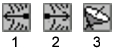
The following table lists the name of each toolbar button—the name appears as a tooltip when you rest the cursor on the button—and its equivalent menu command. To configure the toolbar buttons, see “Configuring the Toolbar” on page 7.
Table 10: Wireless Toolbar Buttons in the Node Editor
| Button | Name in the Toolbar | Equivalent Menu Command |
|---|---|---|
| 1 | Create Radio Receiver | Objects > Create Radio Receiver |
| 2 | Create Radio Transmitter | Objects > Create Radio Transmitter |
| 3 | Create Antenna | Objects > Create Antenna |
Objects Menu
The Objects menu includes the following new operations.
Table 11: New Objects Menu Operations
| Menu item | Description |
|---|---|
| Create Radio Receiver | Creates a radio receiver module. |
| Create Radio Transmitter | Creates a radio transmitter module. |
| Create Antenna | Creates an antenna module. |
These operations work as do the other “create module” operations, as described in “Create <module>” on page 468.
Physical Layout View
With Wireless functionality, the Node Editor contains a physical layout view in addition to the standard logical layout view. You can use the physical layout to set the location of antennas and their targets by dragging them into position. The corresponding antenna module attributes are automatically set to match the object positions.
Note: Targets are shown only when their location is specified in body coordinates. Right-click on an antenna module to quickly change the type of coordinates (body or global) used for that antenna’s targets.
The physical layout has two panes. You can use the top pane to position objects in the horizontal (x-y) plane and the bottom plane to position objects in the vertical (x-z) plane. (You can switch which pane is on top with the “node_editor.physical.show_xy_over_xz” preference.)
Figure 41: Node Editor with Physical Layout
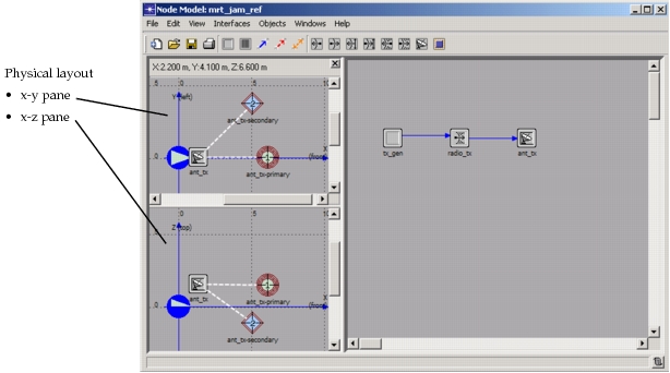
To control whether the physical layout is displayed, choose View > Show/Hide Physical Layout. To change the size of the physical layout, drag the right edge of the physical layout pane.
You can change the appearance of the physical layout from the Physical Properties dialog box (choose View > Set Physical Properties…) and set the default width of the pane with the “node_editor.physical.initial_width” preference.
Miscellaneous Additions
When you right-click on an antenna module, the pop-up menu gives you operations for quickly changing the coordinate type (body or global) used by primary and secondary targets. It also lets you promote the target coordinates.
When you double-click on an antenna module in the workspace, the associated antenna pattern opens in an Antenna Pattern Editor.