Composing a Terrain
This tutorial shows how to compose a terrain by combining elevation data, imagery, and feature data. It recreates a portion of the LittlePond terrain that is included with 3D Network Visualizer. Little Pond is a small detailed area in a suburb of Boston, Massachusetts, U.S.A.
Note: This tutorial shows you how to add props to the LittlePond elevation and image data. However, the tutorial does not ask you to add every type of prop that the complete LittlePond terrain contains. Therefore, at the completion of the tutorial, your terrain will not look exactly like the LittlePond terrain provided with 3D Network Visualizer. To completely recreate the LittlePond terrain, you will have to continue to add props on your own.
The basic steps for composing a terrain are:
- Add elevation data (a terrain patch) (Add Elevation Data (Add a Terrain Patch)).
- Add imagery (Add Imagery).
- Add a feature layer (Add a Feature Layer).
- Add props (Add Props).
Add Elevation Data (Add a Terrain Patch)
The first step in building a terrain is to add elevation data. Elevation data is added using terrain patches. The terrain patch in this tutorial is DTED data that covers about 1° east of Boston, Massachusetts, U.S.A.
Procedure 193: Adding the Terrain Patch
-
Choose File > New Scene. This results in an empty window (Figure 175).
Figure 175: No terrain loaded
-
Choose File > Add Terrain Patch. The Add Terrain Patch dialog box opens and an Open dialog box opens on top of it.
-
In the Open dialog box, navigate to
./data/Terrain/LittlePond/elevation. -
Select
w072n042.dt1. -
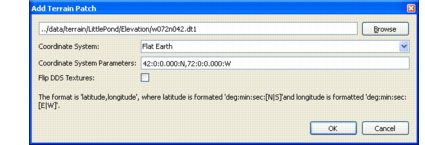
Click OK. Information about this terrain patch is displayed in the Add Terrain Patch dialog box (Figure 176).
Figure 176: Add terrain patch
-
Click OK. The terrain is added to the scene (Figure 177).
Figure 177: Terrain patch added
Add Imagery
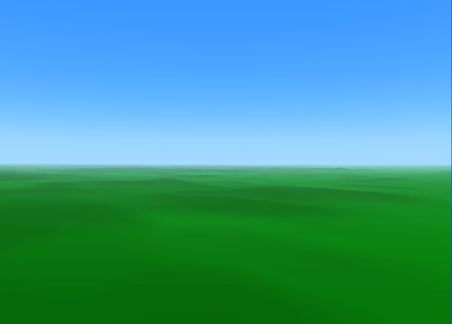
The terrain patch you added in the first step of this tutorial is just elevation data. It has no texture and no features. You can get some sense of its contours by enabling elevation coloring (Figure 178). However, this still does not provide the rich 3D environment you expect to see in a product like 3D Network Visualizer. Now we will add image data.
Figure 178: Elevation coloring
Procedure 194: Adding Image Data
-
Choose Settings > Terrain. The Terrain Settings dialog box opens.
-
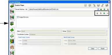
Select the Raster Maps page (Figure 179).
Figure 179: Raster Maps page
-
Click the Add icon (
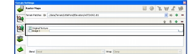
 ) to the right of the Raster Maps label. A line labeled Image 1 is added to the list in the window (Figure 180).
Figure 180: New image
-
Click the Browse button at the right end of the image entry. The Image File dialog box opens.
-
In the Image File dialog box, navigate to
./data/Terrain/LittlePond/imagery. -
Select
W72N42.tif. -
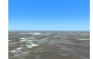
Click OK. The image is listed in the Raster Maps window. To view it, select the checkbox at the left end of the entry. This image adds low resolution imagery over the entire terrain (Figure 181).
Figure 181: Low resolution image
-
Add another image. This time, select
LittlePond.tif. -
Select the checkbox for the
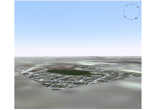
LittlePond.tifimage (Figure 182). A high resolution image is added to the Little Pond Area of the terrain (Figure 183). (The high resolution image might be hard to find. The next section explains how to find it quickly.)Figure 182: Raster Maps page with both images added
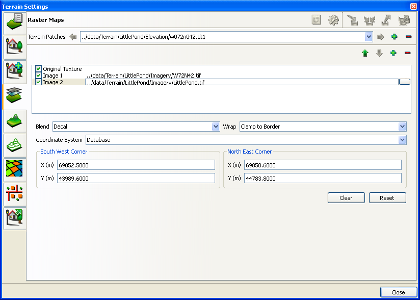
Figure 183: Little Pond image
Finding the High Resolution Image
It is not easy to find the Little Pond image unless you know where to look. To make things easier, we have saved an observer view of the Little Pond image. It will be the starting point for the rest of the tutorial.
Procedure 195: Viewing the Little Pond Image
-
If the Observer Views Panel is not already displayed, choose View > Observer Views Panel.
-
On the Observer Views Panel, click the Load View icon (
 ). The Load and Set Observers dialog box opens.
-
Select
LittlePondTutorial.osrx. -
Click Open. The view should jump to an image similar to Figure 183.
Note: As an alternative to this procedure, you could hide the low resolution image by clearing its selection on the Raster Maps page. Then you could scroll through the terrain until you find the high resolution image.
Add a Feature Layer
The image of Little Pond shows lots of buildings and greenery, but these are just images, not 3D objects. Now we want to add props to the terrain. To do that, we need to add a feature layer that has objects that we can extract.
Procedure 196: Adding the Feature Layer
-
Choose Settings > Terrain. The Terrain Settings dialog box opens.
-
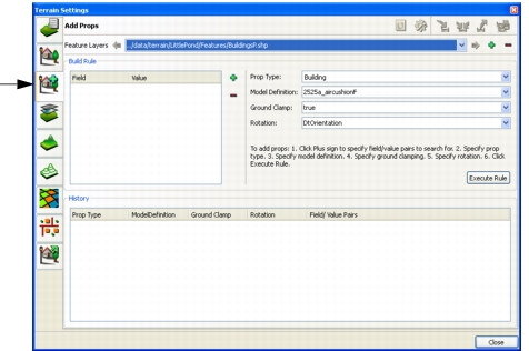
Select the Add Props page (Figure 184).
Figure 184: Add Props page
-
Click the Add icon (
) next to the Feature Layers list. The Select Source File for Feature Layer dialog box opens. -
Navigate to
./data/Terrain/LittlePond/features. -
Select
BuildingsP.shp. -
Click Open. The layer is added to the Add Props page.
Add Props
When you add a prop, 3D Network Visualizer extracts data from a feature layer and maps it to a model definition. You have to tell 3D Network Visualizer what to extract and what to map it to. You do this by building a rule.
Procedure 197: Building a Rule and Extracting Feature Data
-
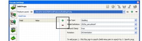
In the Terrain Settings dialog box, on the Add Props page, in the Build Rule group box, click the Add icon (
) (Figure 185). The Build Field/Value Pair dialog box opens.Figure 185: Add build rule
-
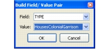
In the Field drop-down list, select TYPE.
-
In the Value drop-down list, select HousesColonialGarrison (Figure 186).
Figure 186: Build Field/Value Pair dialog box
-
Click OK.
-
In the Prop Type drop-down list, select the prop type for the rule. In this case, select Building.
-
In the Model Definition drop-down list, select HousesColonialGarrisonClapboardWhite.
-
In the Ground Clamp box, specify whether or not you want the prop to be ground-clamped.
-
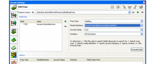
In the Rotation drop-down list, select the orientation of your model. By default, if the GDB or Shapefile has a field called Rotation or DtOrientation, it is automatically selected. The completed rule is illustrated in Figure 187.
Figure 187: Completed rule
-
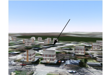
Click Execute Rule. The rule is executed. The Add Props page is updated (Figure 188) and houses are added to the terrain. Zoom in for a better look at them (Figure 189). (You might need to close the Terrain Settings dialog box or move it out of the way to see the terrain.)
Figure 188: Build rule implemented
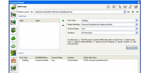
Figure 189: Props added to terrain
If you want to, you can add more buildings by creating rules for some of the other building types available.
Add Vegetation
We will continue the tutorial by adding another feature type.
Procedure 198: Adding Vegetation to the Terrain
-
If the Terrain Settings dialog box is not open, choose Settings > Terrain.
-
Select the Add Props page.
-
Click the Add icon (
) next to the Feature Layers list. The Select Source File for Feature Layer dialog box opens. -
Select
./data/Terrain/LittlePond/features/VegetationP.shp. -
Click Open. A new feature layer is added to the list.
-
In the Build Rule group box, click the Add icon (
). The Build Field/Value Pair dialog box opens. -
In the field drop-down list, select VEG.
-
In the Value drop-down list, select TreesBigLeafMaple.
-
Click OK.
-
In the Prop Type drop-down list, select Tree.
-
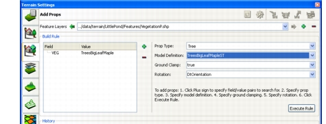
In the Model Definition drop-down list, select TreesBigLeafMapleST. The build rule should look like (Figure 190).
Figure 190: Rule for big leaf maples
-
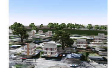
Click Execute Rule. The page is updated and trees are added to the terrain (Figure 191).
Figure 191: Little Pond with maples
You can build additional rules to add other types of vegetation to the terrain. When you are done, you can create another feature layer with the architecture shapefile (InfrastructureP.shp) and add light posts, fire hydrants, and street signs to the terrain.