Deploying the Applications
After you have configured your applications, profiles, and tasks, you are ready to deploy these profiles on individual workstations, servers, and LANs. Typically, profiles are specified on workstations or LANs, since they are traffic sources. However, a profile may be deployed on a server if the server acts as a source for any application task. This implies that if you have configured a task table such that the server is an independent source, you should ensure that you support that profile on the server object. See Custom Application for details on the custom application task configuration.
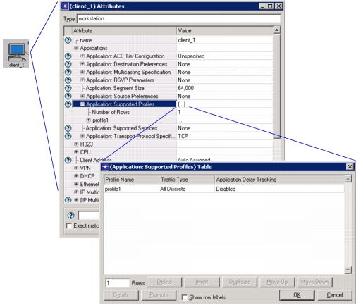
This section describes how to deploy applications and destination preferences, and how to add LAN nodes to your network model to represents clusters of workstations. Deploying applications with the Application Deployment wizard is an automated way to set node attributes. In the following figure, you can see that the “engineer” profile is deployed to the workstation. The wizard provides a way to deploy applications into many nodes in the model simultaneously.
Figure 58: Profile Deployed to a Workstation
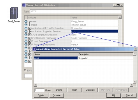
In addition to deploying applications to workstations, you must deploy supported services to servers in your network model. For example, one server might support Email and HTTP services, while another server might support database operations. You can expedite this process by using the Application Deployment wizard.
Figure 59: Configuring Servers to Support Applications
Application Deployment Wizard
The Application Deployment wizard automates the deployment of supported profiles and services to nodes in your network model. Using the Application Deployment wizard, you can
- view and modify the application deployment
- deploy profiles that are already defined in the profile configuration object
- populate the individual node attributes automatically
Figure 60: Application Deployment Wizard
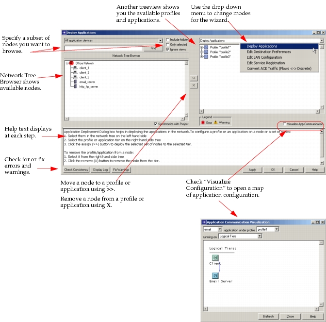
The following procedure describes how to use the Application Deployment wizard to deploy profiles quickly.
Procedure 8: Deploying Profiles with the Application Deployment Wizard
-
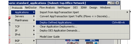
Open the Application Deployment wizard by choosing the menu selection Protocols > Applications > Deploy Defined Applications… or by the shortcut key combination Ctrl + Alt + A.
Figure 61: Open Application Deployment Wizard
-
Select the node(s) in the left treeview to which you wish to deploy a profile or application.
Note: Remember to assign profiles to LAN nodes in your network also.
-
Select the profile or application tier in the right treeview.
-
Click the “>>” button to assign node(s) to the selected profile or application.
-
Check the consistency of the configuration, after you have assigned all nodes to the appropriate profiles, by pressing the Check Consistency button.
-
Correct any configuration errors identified during the consistency check.
-
Press the Fix Warnings button to automatically correct warning conditions.
-
Click Apply to apply the deployment to the network model, when you are satisfied with your configuration.
-
Click OK to leave the Application Deployment wizard.
End of Procedure 8
Servers are unique from workstations in many ways. Not only do they support a variety of services, they can also be made to model a wide variety of servers in your operational network. For example, if you have a dual processor system, you may want to increase the number of CPU resources in the server attributes. See the following procedure for more information.
Procedure 9: Configuring Specific Server Attributes
-
Right-click on the server node and Edit Attributes…
-
Set the Server Address attribute with the unique TPAL name.
-
Set CPU attributes. 3.1 Set CPU > CPU Resources Parameters.
“Number of Resources” and “Processing Speed Multiplier” both have a linear effect on the processing time of a job. For example, suppose by default “Number of Resources” = 1 and “Processing Speed Multiplier” = 1.0, completing a job in 5 seconds. If you increased “Number of Resources” to 2 and left “Processing Speed Multiplier” = 1.0, the same job will take 2.5 seconds to complete. Another example: If “Number of Resources” = 1 and “Processing Speed Multiplier” is 2.0, the job will take 2.5 seconds to complete. **Note:** Processing speed is based on the application in use. To find out the default processing speed for an application, expand Applications > Application: Supported Services and examine the Processing Speed (bytes/sec) attribute in the definition table for the specified application. The processing time required is based on the response size for FTP Get, Email Recv, Database Query application types and on the request sizes for the rest of the applications. **Figure 62: CPU Attributes** 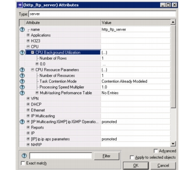3.2 Set CPU > CPU Background Utilization. Add as many rows as are necessary to specify utilization percentages at a variety of start times within the simulation.
The CPU background utilization determines how much of the CPU processing power is available for the jobs. For example, if, in the absence of any CPU background utilization (0%), a job took 10 seconds to complete, then if the CPU background utilization is 50%, the same job will take 20 sec to complete (since it gets only 50% of CPU). If the CPU background utilization is 75%, the same job will take 40 sec to complete (since it gets only 25% of CPU). -
Set Task Contention Mode.
End of Procedure 9
Deployment Example
As described in Procedure 8, you can easily assign applications and profiles to any node in the network model. Here is a practical example of how the Application Deployment wizard is used:
Figure 63: Example of Custom Application Deployment
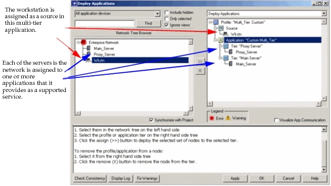
In the multi-tier custom application shown here, each layer of the profile represents a different level of communication. The workstation is the source of the application—when a user presses Enter to send a database request, for example. In the application itself, there are two servers: a proxy server and a main server. “Tier: Proxy Server” represents a layer of the custom application. In Figure 63 the node “Proxy_Server” is assigned to the tier so that our source will talk to this server at this level in the application.
Edit Destination Preferences
Each application uses a symbolic name to refer to a server. For example, if you have set the symbolic server name of the E-mail application to “Corporate_Email_Server”, you must resolve this reference so that the symbolic name refers to an actual server object on the network. The advantage of using symbolic names is that you can define an application once with a symbolic name. You can then resolve the symbolic name to different actual names on different workstations.
For example, you can resolve the Corporate_Email_Server described above as Server_192 for all engineers and as Server_198 for all sales people. When you set destination preferences, you assign a node to a symbolic name and set a weight value for its preferability to traffic.
Note: If you do not set any destination preferences, the server will be selected at random from the servers that support the application of interest.
This is another task you can perform with the Application Deployment wizard.
Figure 64: Setting the Destination Preference with the Application Deployment Wizard
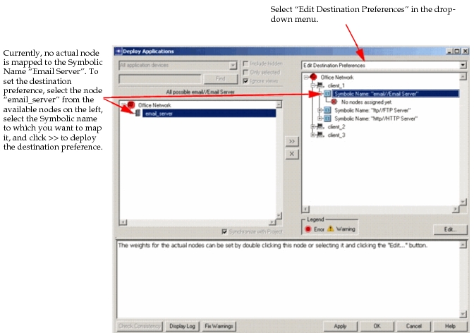
The default weight of a destination preference is 10. The higher the number, the greater the likelihood the server will be chosen during a simulation.
Figure 65: Effect of Server Weight on Destination Preference
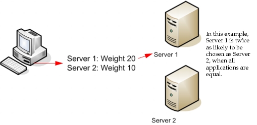
For example, if you had five Email servers in your network model, you would map all five to the symbolic name “email/Email Server” in the example shown in Figure 64. Each node would be assigned a weight of 10, automatically. You can click on the “Edit…” button to set the weight to any number. If you want the traffic to use a particular server, set that preference to a higher weight than on other nodes.
Using Multiple Servers for an Application
The usual method of setting Destination Preferences assigns only one server (chosen randomly) to an application. You might want to assign several servers, for example, to increase traffic. There are two symbol map values that can simplify the assignment of multiple servers to an application.
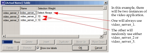
Normally, for each server, you add one row to the Application: Destination Preferences > Actual Name attribute and set Name in each row to a different server. Instead, if you want to create an application instance for every server that supports that application, you can simply add one row and set Name to “All Supporting Servers”. Any additional rows will be ignored, and Selection Weight has no effect.
If you want to use only some of the supporting servers, add a row for each server and set Selection Weight to “Select Always”. This will create one application instance for each of these servers (plus one additional instance with a random server, if there are also servers with numeric weights).
Figure 66: Effect of “Select Always” on Destination Preference
Note: These symbol maps are not available in the Application Deployment wizard. To use them, you must edit attributes on the desired nodes.
Edit LAN Configuration
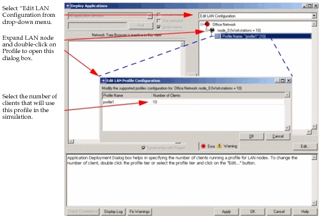
When you use LAN nodes in your network model, you must deploy profiles to each one used in your simulation. After deploying the profile, select the number of workstations in the LAN model for your simulation.
Figure 67: Edit LAN Configuration
Deploying an Application from Transaction Analyzer Files (Manual Workflow)
This workflow describes how to add a Transaction Analyzer application task by configuring the Profile, Application, and Task definitions manually.
A Transaction Analyzer-generated scenario includes three configuration objects that define when and how a AppTransaction Xpert file is run during a discrete event simulation. Including a AppTransaction Xpert file in an existing network scenario involves the following three steps:
- Include the AppTransaction Xpert file in the Task configuration object. This object contains information on each specific task to be run during a discrete event simulation. First add another row to the Task Specification table; then click in the Transaction Model Name field, and choose the AppTransaction Xpert file name from the pull-down menu.
- Create an application definition in the Application configuration object. This object contains information about how a specific task should be run. Creating a definition is a two-step process: 2.1 First create a row in the Application Definitions attribute table. 2.2 Then create a task description for this attribute by “drilling down” into the new compound attribute, like so: Description > Custom > Task Description. Create a row in the Task Description table, then click in the Task Name field and select the task from the pull-down menu. You can include multiple AppTransaction Xpert files in this table, and use the Task Weight and Task Ordering attributes to specify when and how the defined application runs the individual tasks.
- Add the application to an application profile in the Profiles configuration object. An application profile includes a set of one or more application definitions (specified by the Applications attribute) and specifies when and how often these applications are run (specified by the Operation Mode, Start Time, Duration and Repeatability attributes). You can create a profile for your application definition (by adding another row to the Profile Configuration table) or add it to an existing profile.