Adding a Model to 3D Network Visualizer
This tutorial shows how to add a new model to a 3D Network Visualizer application. To help you with the tutorial, 3D Network Visualizer includes a model of an F/A-18 Hornet that is not mapped to any entities.
The basic steps are:
- Create a model definition (Create a Model Definition).
- Add an element definition (Add an Element Definition).
- Map the new model to an entity or object type enumeration (Add a Model Mapping).
- Test the new model (Test the Model Mapping).
Create a Model Definition
Procedure 207: Creating the Model Definition
-
Choose Settings > Visual Model Editors. The Visual Model Editors dialog box opens.
-
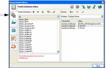
Select the Model Definition Editor page (Figure 210).
Figure 210: Model Definition Editor page
-
Optionally, filter the model definitions in the list to just show entity model definitions. (For details, please see “Filtering the List of Model Definitions“ on page 330.)
-
Click the Add icon (
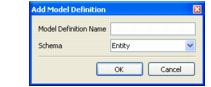
 ) next to the Model Definitions label. The Add Model Definition dialog box opens (Figure 211).
Figure 211: Add Model Definition dialog box
-
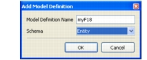
Type a name for the new model definition, for example,
myF18. -
If you filtered the model definition list, the Schema box says Entity. If not, in the Schema drop-down list, select Entity. The dialog box now looks like Figure 212.
Figure 212: New model definition
-
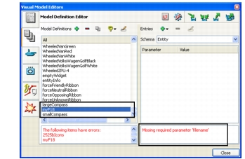
Click OK. The new definition is added to the list (Figure 213). It does not have any parameters specified yet, so 3D Network Visualizer prints an error message. Now you must specify the model file for this model definition.
Figure 213: New model definition in list
-
Select the new model definition.
-
Click the Add Parameter icon (
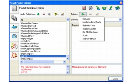
 ). A list of parameters is displayed (Figure 214).
Figure 214: List of parameters
-
Select filename. It is added to the parameter list.
-
Click the value for the parameter. A file selection dialog box opens.
-
Navigate to
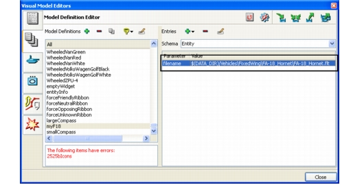
./data/Vehicles/FixedWing/FA-18_Hornetand selectFA-18_Hornet.flt. -
Click OK. The value is updated (Figure 215).
Figure 215: Model definition parameter
Add an Element Definition
Procedure 208: Adding an Element Definition
-
Choose Settings > Visual Model Editors. The Visual Model Editors dialog box opens.
-
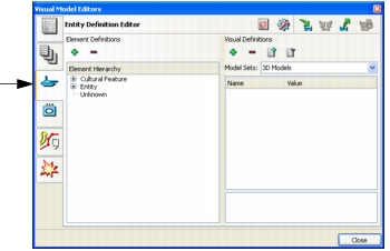
Select the Entity Definition Editor page (Figure 216).
Figure 216: Entity Definition Editor page
-
Expand the Entity section of the hierarchy and then expand the Air section.
-
Select Fixed Wing.
-
Click the Add icon (
) next to the Entity Definitions label. The Create Element Definition dialog box opens. -
Type a name for the new entity definition, for example,
myF18. -
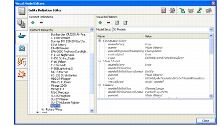
Click OK. An entry called myF18 is added to the list of fixed wing entities (Figure 217). It has the same list of visualizers as the fixed wing parent level.
Figure 217: New entity definition
-
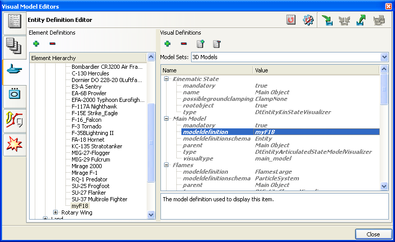
Scroll through the list of visualizers until you find the Main Model Visualizer. This visualizer specifies the model definition that this element should use.
-
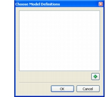
Click the Value column for the modelDefinition attribute to make it editable. The Choose Model Definitions dialog box opens (Figure 218).
Figure 218: Choose Model Definitions dialog box
-
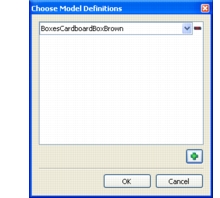
Click the Add (
) icon. A drop-down list of model definitions is added to the dialog box (Figure 221).Figure 219: Choose Model Definitions dialog box with list of definitions
-
Select the new model definition (myF18) and click OK. The model definition is now specified (Figure 220).
Figure 220: Model Definition for Model Visualizer
-
Close the Visual Model Editors dialog box.
Add a Model Mapping
Now, you have to map the new model definition to an entity type enumeration.
Procedure 209: Adding a Model Mapping
-
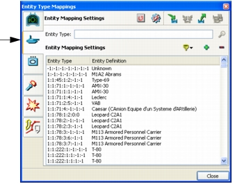
Choose Settings > Entity Type Mappings. The Entity Type Mappings dialog box opens.
-
Select the Entity Mapping Settings page (Figure 221).
Figure 221: Entity Mappings page
-
Click the Filter icon (
 ).
-
In the list, select Entity > Air > Fixed Wing. (This does not change the Entity Mapping Settings list; it filters the list in the Create New Entity Type Model Mapping dialog box.
-
Click the Add icon (
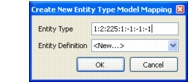
). The Create New Entity Type Model Mapping dialog box opens (Figure 222). It lists a default entity type enumeration.Figure 222: Create New Entity Type Model Mapping dialog box
-
In the Entity Type text box, type the enumeration you want to map to the new model mapping. (The enumeration for an F/A18 is 1:2:225:1:9:1:-1.)
Note: 3D Network Visualizer already has an F/A18 mapped to this enumeration. However you can map multiple model definitions to an enumeration. When an entity type that has multiple model definitions mapped to it is discovered in a simulation, 3D Network Visualizer randomly assigns a model definition from among those mapped to the entity type.
-
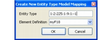
In the Entity Definition drop-down list, select the model definition that you added in the previous procedure (myF18) (Figure 223).
Figure 223: Create new model mapping
-
Click OK.
-
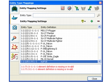
The new model mapping is added to the list.
Figure 224: New model mapping
Test the Model Mapping
It is a good idea to test the new model mapping to see if the correct model is being displayed. You can test a model by running a simulation that has the entity or object type, or you can perform the simple test described here.
Procedure 210: Testing a Model
-
Open a terrain database that has easily identifiable props. For the purposes of this tutorial, open the Makland terrain.
-
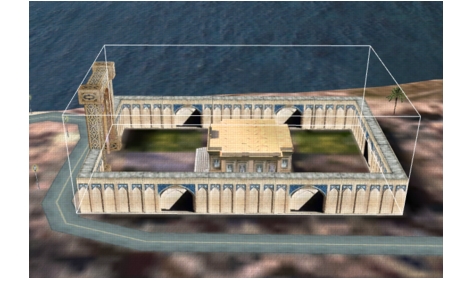
In the 3D Network Visualizer window, move the observer so that you are viewing the palace on top of the hill near the town in Makland.
-
Click the palace to select it (Figure 225).
Figure 225: Palace
-
Choose Settings > Terrain. The Terrain Settings dialog box opens.
-
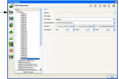
Select the Edit Existing Props page. The list of props shows that Building26, the palace, is selected (Figure 226).
Figure 226: Edit Existing Props page
-
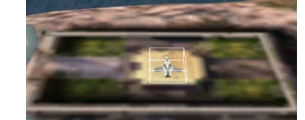
In the Model Definition drop-down list, select the model definition that you added earlier in this tutorial (Figure 227). The model of the palace is replaced with the model for the F/A-18 (Figure 228). If this is the model that you wanted to add, then you know that you completed the procedure correctly. If this is not the model, you expected, check the filename you specified for the model definition.
Figure 227: Changed model definition
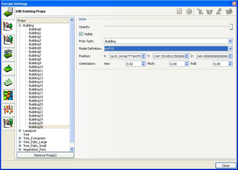
Figure 228: F/A-18 replaces the palace
-
If you are going to use this terrain for simulations, change the model definition back to Use Extended Geometry.