FHSS Support
Frequency hopping (FHSS) is a well known spread spectrum modulation technique used to mitigate the effects of narrow-band noise. The effectiveness of frequency hopping depends on the number of physical channels available for hopping (hop-set), as well as the rate at which channels are switched (hopping rate or dwell time).
In FHSS, the transmitting node continuously hops from one channel frequency to another as it transmits information, thus limiting the impact of any interference prevalent in any single channel. The hop set is either known in advance to the transmitter and the receiver or is determined independently by the transmitter and the receiver based on a unique identifier and possible channel set. Thus, for FHSS to work, all the nodes in a particular network must have or share the same channel information so they can synchronously transmit and receive as they hop over multiple channels.
The FHSS model lets you execute radio network simulations with higher fidelity modeling of physical layer effects. Thus, the simulation results will more accurately reflect radio behavior in terms of resistance to interference.
The FHSS model is a generic model capable of being incorporated into any radio model with minimal change to the radio model code. FHSS is a physical layer effect, therefore it is modeled in the pipeline stages of the transmitter and receiver.
The following two approaches are supported in the FHSS model. You can configure the appropriate model based on required fidelity.
Abstract FHSS model
In this approach, the benefit of using FHSS is incorporated into the simulation as an average correction factor (the processing gain). This approach is the default option for FHSS modeling, as it adds minimal overhead to simulation execution time.
Detailed FHSS model
In this approach, the behavior of FHSS is modeled explicitly. Here, the correct channel properties of the transmitter and receiver are maintained and updated for each dwell time duration. During each transmission, an accurate check is performed on the channels for each interfering station. Narrow-band interfering stations which are out-of-band are ignored. This approach automatically results in accurate measurement of signal-to-noise ratio, thus capturing the effects and benefits of FHSS.
Model Attributes
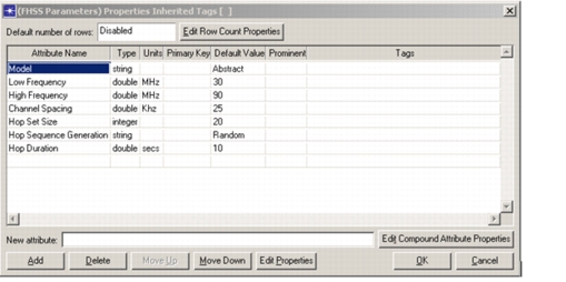
The FHSS attributes are all specified within the FHSS Modeling compound attribute. The attribute structure is available as a public attribute: oms_fhss_public_attr.ad.m.
- Model – Specifies whether the radio will use the abstract model or the detailed model
- Low Frequency – Specifies the lower boundary of the frequency spectrum used by the radio
- High Frequency – Specifies the upper boundary of the frequency spectrum used by the radio
- Channel Spacing – Specifies the spacing between the channels for FHSS. Typically, the channel spacing should be the same as the channel bandwidth.
- Hop Set Size – Defines the number of channels used for FHSS
- Hop Sequence Generation – Specifies the method used to generate the hop sequence. The hop sequence can be randomly selected or can be formed by contiguous selection of channels.
- Hop duration – Specifies the duration for which each node resides in a particular channel
Figure 16: FHSS Modeling Attribute
Incorporating the FHSS Model into a Radio Model
The FHSS module is a standalone module that provides APIs to generate frequency hopping patterns, perform channel matching, and perform bookkeeping based on TDAs and channel object state information.
The following steps must be performed to incorporate FHSS behavior into an existing or new radio model.
Adding the FHSS Attributes
The FHSS attributes are specified within the compound attribute “FHSS Modeling”. The attribute structure is available as a public attribute, “oms_fhss_public_attr.ad.m”.
FHSS attributes should be common to all nodes in the network and should preferably be added to a network-level configuration node. If such a node is not available, then the FHSS attribute can be added to individual nodes. However, when added to individual nodes, additional mechanisms should be provided to ensure that all nodes have the same configuration.
Note: The FHSS package does not provide any conformance checks on the consistency of the attributes for different nodes within a single FHSS group. The primary reason for this is that the package does not enforce which nodes should include these attributes and does not enforce how these attributes are populated (e.g., user-defined, auto-calculated, through custom GUI, etc.).
Registering with the FHSS Package
A radio process should register with the FHSS package to invoke the FHSS functionality. Typically, this registration is performed in the MAC process as all the necessary information is available in the MAC process model.
The MAC process initializes FHSS functionality for each channel in the transceiver object separately.
The initialization function, Oms_FHSS_Initialize (), takes the following inputs:
- Transmitter or Receiver Flag – OmsC_FHSS_Transmit if transmitter, and OmsC_FHSS_Receive if receiver channel
- Tx/Rx objid – The object id of the transmitter or the receiver
- Tx/Rx channel objid – The object id of the specific channel
- Channel bandwidth – The channel bandwidth of the channel, if different from the value in the channel object. This parameter provides flexibility to handle cases in which the MAC maintains state regarding the bandwidth, and the channel object has a bandwidth that covers the complete technology spectrum. When the package has to use the channel object attribute “bandwidth,” then pass the value OMSC_FHSS_NOT_USED for this parameter.
- FHSS attribute compound objid – The object id of the FHSS compound attribute
- User Rx/Tx state pointer – The user state information maintained or used by the MAC process
- Number of hop sequences – Typically this is set to “1” to indicate that only one frequency hopping sequence needs to be created for the channel. Sometimes the MAC process (or underlying PHY architecture) maintains an internal state to identify the operational channel. In this case, this parameter specifies the number of sequences that need to be created.
- Array of seeds – Specifies the seed values to be used for generating frequency hopping sequences. If only one sequence has to be generated, then pass a pointer to variable. If more than one sequence is to be generated then pass an array of appropriate size containing the seed values.
The code below shows example integration.
/* FHSS support function                            */

void
FHSS_functionality_check ()
	{
	Objid                 fhss_objid;
	Objid                 tx_objid, rx_objid;
	Objid                 txch_objid, rxch_objid;
	Objid                 chann_objid;
	double                rx_net_id;
	double                tx_net_id;
	int                   child_count;
	FHSST_State_Info*     return_state_ptr;
	int                   temp;

	FIN (renad_FHSS_functionality_check ());

	//Get the FHSS attribute.
	op_ima_obj_attr_get (my_module_id, "FHSS Modeling", &fhss_objid);

	child_count = op_topo_child_count (fhss_objid,OPC_OBJTYPE_GENERIC);

	//If the child count is 0 then FHSS is disabled.
	if (child_count == 0)
		FOUT;

	/* Gather other inputs before calling the FHSS init function.  */
	//In this MAC the net_id is used as seed value.
	op_ima_obj_attr_get (my_node_id, "tx_0.net_id", &temp);
	tx_net_id = temp;

	/* In model only the tx has net_id.  So we will use the same   */
	/* net_id for Rx side.                                         */

	rx_net_id = tx_net_id;

	/* Get the rx and tx objid id and channel ids.                 */
	rx_objid = op_topo_assoc (my_module_id, OPC_TOPO_ASSOC_IN,
	OPC_OBJTYPE_RARX, 0);
	tx_objid = op_topo_assoc (my_module_id, OPC_TOPO_ASSOC_OUT,
	OPC_OBJTYPE_RATX, 0);

	op_ima_obj_attr_get (rx_objid, "channel", &chann_objid);
	rxch_objid = op_topo_child (chann_objid, OPC_OBJTYPE_RARXCH, 0);

	op_ima_obj_attr_get (tx_objid, "channel", &chann_objid);
	txch_objid = op_topo_child (chann_objid, OPC_OBJTYPE_RATXCH, 0);

	/* Note that this radio will have only 1 channel therefore     */
	/* only one hop sequence and also no rx or tx state is currently */
	/* used.                                                       */

	/* Initialize the transmitter FHSS.                            */
	/* If needed we can store the returned state information.      */

	return_state_ptr = Oms_FHSS_Initialize (FHSSC_Transmit, fhss_objid,
	OPC_NIL, tx_objid,txch_objid, FHSSC_NOT_USED, 1, &tx_net_id);

	/* Initialize the receiver FHSS.                               */
	/* If needed we can store the returned state information.      */

	return_state_ptr = Oms_FHSS_Initialize (FHSSC_Receive, fhss_objid,
	OPC_NIL, rx_objid, rxch_objid, FHSSC_NOT_USED, 1, &rx_net_id);

	FOUT;
	}
Calling the FHSS Channel Match Function
The channel match pipeline stage should be modified to call channel match API provided by the FHSS package.
The API - Oms_FHSS_Channel_Match_Determine - returns either OmsC_FHSS_Not_Supported or OmsC_FHSS_Channel_Match_True or OmsC_FHSS_Channel_Match_False.
The FHSS channel match will attempt to perform a channel match if both the transmitter and receiver have FHSS appropriately configured. In this case, the channel match TDA is set by the package. A custom TDA also stores the channel overlap.
When the package returns OmsC_FHSS_Not_Supported, then the default functionality of channel match stage should be performed.
The code below shows how the dra_chanmatch stage should be modified.
FIN_MT (dra_chanmatch (pkptr));

/* Obtain transmitting channel attributes. */
tx_freq		= op_td_get_dbl (pkptr, OPC_TDA_RA_TX_FREQ);
tx_bw		= op_td_get_dbl (pkptr, OPC_TDA_RA_TX_BW);
tx_drate	= op_td_get_dbl (pkptr, OPC_TDA_RA_TX_DRATE);
tx_code	= op_td_get_dbl (pkptr, OPC_TDA_RA_TX_CODE);
tx_mod	= op_td_get_ptr (pkptr, OPC_TDA_RA_TX_MOD);

/* Obtain receiving channel attributes. */
rx_freq		= op_td_get_dbl (pkptr, OPC_TDA_RA_RX_FREQ);
rx_bw		= op_td_get_dbl (pkptr, OPC_TDA_RA_RX_BW);
rx_drate	= op_td_get_dbl (pkptr, OPC_TDA_RA_RX_DRATE);
rx_code	= op_td_get_dbl (pkptr, OPC_TDA_RA_RX_CODE);
rx_mod	= op_td_get_ptr (pkptr, OPC_TDA_RA_RX_MOD);

/* Check of FHSS based channel match.      */
match_type = Oms_FHSS_Channel_Match_Determine (pkptr, OMSC_FHSS_NOT_USED, OMSC_FHSS_NOT_USED, tx_freq, tx_bw, tx_mod, tx_code, tx_drate, rx_freq, rx_bw, rx_mod, rx_code , rx_drate);

if (match_type == OmsC_FHSS_Not_Supported)
	{
	/* FHSS not used -- perform regular check. */
	/* For non-overlapping bands, the packet has no */
	/* effect; such packets are ignored entirely. */
	if ((tx_freq > rx_freq + rx_bw) || (tx_freq + tx_bw < rx_freq))
		{
		op_td_set_int (pkptr, OPC_TDA_RA_MATCH_STATUS, OPC_TDA_RA_MATCH_IGNORE);
		FOUT;
		}

	/* Otherwise check for channel attribute mismatches which would */
	/* cause the in-band packet to be considered as noise.          */
	if ((tx_freq != rx_freq) || (tx_bw != rx_bw) ||
		(tx_drate != rx_drate) || (tx_code != rx_code) || (tx_mod != rx_mod))
		{
		op_td_set_int (pkptr, OPC_TDA_RA_MATCH_STATUS, OPC_TDA_RA_MATCH_NOISE);
		FOUT;
		}

	/* Otherwise the packet is considered a valid transmission which */
	/* could eventually be accepted at the error correction stage.   */
	op_td_set_int (pkptr, OPC_TDA_RA_MATCH_STATUS, OPC_TDA_RA_MATCH_VALID);

	}
Using the FHSS Channel Overlap TDA
In the power pipeline stage, the channel overlap is calculated to determine the in-band transmit power. However, if the channel match is performed by the FHSS package, then the channel overlap is stored in a custom TDA.
The standard power pipeline stage should be modified to check for the channel overlap TDA first, and if no valid channel overlap has been recorded, only then should it default to standard behavior.
The code below shows the modified dra_power stage.
/* The base of the overlap band is the highest base frequency. */
	if (rx_base_freq > tx_base_freq)
		band_min = rx_base_freq;
	else
		band_min = tx_base_freq;

	/* The top of the overlap band is the lowest end frequency. */
	if (rx_base_freq + rx_bandwidth > tx_base_freq + tx_bandwidth)
		band_max = tx_base_freq + tx_bandwidth;
	else
		band_max = rx_base_freq + rx_bandwidth;

	channel_overlap = Oms_FHSS_Channel_Overlap_Get (pkptr) ;
	if (channel_overlap == OMSC_FHSS_NOT_USED)
		{
		channel_overlap = (band_max - band_min) / tx_bandwidth;
		}

	/* Compute the amount of in-band transmitter power. */
	in_band_tx_power = tx_power * channel_overlap;
Using the FHSS Processing Gain TDA
When the abstract FHSS model is used, the FHSS package will determine the processing gain and store the value in a custom TDA.
The SNR pipeline stage should be modified to read the processing gain and apply this to the SNR value. Note that this processing gain is different from the “processing gain” channel attribute.
The code below shows the modified standard SNR stage.
void
dra_snr_mt (OP_SIM_CONTEXT_ARG_OPT_COMMA Packet * pkptr)
	{
	double		bkg_noise, accum_noise, rcvd_power;
	double		FHSS_proc_gain = 1.0;

	/** Compute the signal-to-noise ratio for the given packet. **/
	FIN_MT (dra_snr (pkptr));

	/* Get the packet's received power level. */
	rcvd_power = op_td_get_dbl (pkptr, OPC_TDA_RA_RCVD_POWER);

	/* Get the packet's accumulated noise levels calculated by the */
	/* interference and background noise stages. */
	accum_noise = op_td_get_dbl (pkptr, OPC_TDA_RA_NOISE_ACCUM);
	/* Check if FHSS proc gain has been set. */
	if (accum_noise > 0.0)
		FHSS_proc_gain = Oms_FHSS_Processing_Gain_Get (pkptr);

	bkg_noise = op_td_get_dbl (pkptr, OPC_TDA_RA_BKGNOISE);

	/* Assign the SNR in dB. */
	op_td_set_dbl (pkptr, OPC_TDA_RA_SNR,
		10.0 * log10 (rcvd_power / (accum_noise/FHSS_proc_gain + bkg_noise)));

	/* Set field indicating the time at which SNR was calculated. */
	op_td_set_dbl (pkptr, OPC_TDA_RA_SNR_CALC_TIME, op_sim_time ());

	FOUT
	}
Using the FHSS Package to Retrieve User Channel State Information
The FHSS package provides an API to retrieve the channel state information. This API will return the default channel object state if FHSS is not used or disabled. If FHSS is enabled, then the API will retrieve the user state information from the FHSS state information.
All access to channel state information has to be performed via this API to ensure consistent operation in all pipeline stages.
The code below shows how the channel state information is accessed in the dra_power stage.
/* The receiving node is enabled.  Get  */
/* the address of the receiver channel. */
rx_ch_obid = op_td_get_int (pkptr, OPC_TDA_RA_RX_CH_OBJID);

/* Access receiver channels state information.  */
rxch_state_ptr = (DraT_Rxch_State_Info *) Oms_FHSS_User_Channel_State_Get (rx_ch_obid);
FHSS Functions
The functions that implement the buffer management (oms_buffer) operations are described in the following sections.