Configuring WiMAX Parameters
Once you have built your topology and added traffic to the network, you are ready to run simulations and perform analysis. You may, however, want to customize your configuration. This section describes the basic steps needed to customize WiMAX functionality in a network model, which comprises the following steps.
- Defining Service Classes
- Configuring Efficiency Mode
- Configuring Physical Layer (PHY) Profiles
- Configuring 802.16j
- Configuring Uplink Power Control
- Configuring Power Saving
- Configuring PUSC Segmentation
- Configuring MIMO
- Defining Service Flows
- Assigning Traffic to Service Classes
- Configuring Physical Layer Parameters
- Configuring Mobility
The steps listed above are sufficient for running a simulation with the default parameters. After completing the basic setup, you might want to examine and modify other WiMAX attributes in the WiMAX configuration object and in the WiMAX Parameters attribute on subscriber station and base station nodes. Detailed descriptions of all attributes are included in the Attributes dialog box within the software.
Defining Service Classes
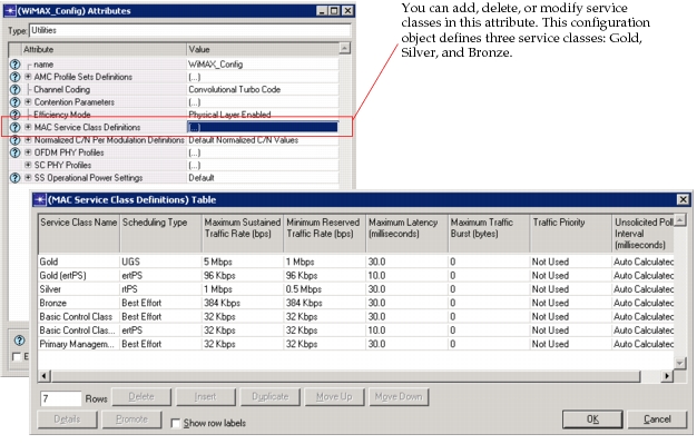
A service class groups the QoS requirements of service flows. Each scenario that includes WiMAX must have a WiMAX configuration object, and the service classes must be defined in the MAC Service Class Definitions attribute of the WiMAX configuration object. Service classes are associated with service flows on subscriber nodes.
By default, the configuration object defines three service classes: Gold, Silver, and Bronze. You can modify the parameters of each of these service classes or replace the default service classes with your own classes. Although you can configure multiple service classes to use the same scheduling type, each service class must have a unique name.
Figure 638: Defining WiMAX Service Classes
Configuring Efficiency Mode
Depending on the goals of your WiMAX simulation study, you can configure the model to use a limited set of features. Several efficiency modes are included in the WiMAX model.
- Efficiency Enabled—Comprises MAC (fluid flow model) with no PHY. The most common use case for this efficiency mode is capacity planning.
- Framing Module Enabled—Comprises MAC (frame-by-frame) and abstracted PHY. The most common use case is modeling QoS and application deployment planning.
- Physical Layer Enabled—Comprises MAC (frame-by-frame) and PHY. The most common use case is modeling PHY transmission and channel effects, such as co-channel interference, multipath fading, and pathloss effects.
- Mobility and Ranging Enabled—Comprises the features of "Physical Layer Enabled" with Mobility and Ranging enabled. The most common use case is Mobility modeling.
Note: Even if you configure mobility, ARQ, framing, or physical layer attributes, their effects are only modeled when using an efficiency mode that supports their features. Refer to Table 259 for specific information for each feature.
The following table lists the highest efficiency mode required for each feature.
Table 259: WiMAX Efficiency Modes Supported by Feature
| Feature | Highest Efficiency Mode Supported |
|---|---|
| Admission Control¹ | Efficiency Enabled |
| IPv6² | Efficiency Enabled |
| ARQ | Framing Module Enabled |
| Aggregated Bandwidth Requests | Framing Module Enabled |
| Overbooking and Underbooking for Admission Control | Framing Module Enabled |
| Multi-level ertPS³ | Framing Module Enabled |
| Piggyback Bandwidth Requests | Framing Module Enabled |
| PUSC Segmentation | Framing Module Enabled |
| Reserved Subframe Capacity | Framing Module Enabled |
| Higher-Layer Broadcast | Physical Layer Enabled |
| HARQ | Physical Layer Enabled |
| MIMO | Physical Layer Enabled |
| Power Saving | Physical Layer Enabled |
| 802.16j | Mobility and Ranging Enabled |
| AMC | Mobility and Ranging Enabled |
| ASN | Mobility and Ranging Enabled |
| Control Messages over PHY⁴ | Mobility and Ranging Enabled |
| Power Control | Mobility and Ranging Enabled |
| Ranging | Mobility and Ranging Enabled |
| Scanning and Handover | Mobility and Ranging Enabled |
Note 1: In Efficiency Enabled mode, there is a single scheduler for both uplink and downlink, because there is no frame timing accounted for. Therefore, no uplink/downlink boundaries can be established, and the corresponding resources (for UL/DL) cannot be determined. Starting in Framing Module Enabled mode, separate resources can be assigned to uplink and downlink separately.
Note 2: With Efficiency Enabled or Framing Module Enabled mode, IPv6 ND simulation efficiency should be enabled.
Note 3: With Framing Module Enabled and Physical Layer Enabled modes, this feature will work without the CQICH message (min allocation size will be 1 MAC header + 1 grant management subheader). With Mobility and Ranging Enabled mode, min allocation size will be zero.
Note 4: All control messages, except for the MOB_HO-IND message, are sent over the physical layer when the efficiency mode is set to Mobility and Ranging Enabled.
Generally, setting the Efficiency Mode to Physical Layer Enabled or Framing Module Enabled generates more accurate delay statistics due to the increased granularity introduced by framing and physical layer features.
Configuring Physical Layer (PHY) Profiles
For modeling studies that use the model's framing features, you need to configure the OFDM PHY Profiles attribute to set up the SOFDMA physical layer profile you need. As mentioned in Configuring Efficiency Mode, you need to set the efficiency mode to Framing Module Enabled, Physical Layer Enabled or Mobility and Ranging Enabled to model the framing mechanisms in WiMAX connections.
PHY layer profiles are used for the following:
- Estimating link capacities during admission control
- Determining uplink/downlink boundary information using the configured frame structure information
- Determining PHY-layer overheads
Note: Some of the PHY attributes are not used in the Framing Module Enabled mode.
Configuring 802.16j
By default, the WiMAX configuration object has two rows in the OFDM PHY Profiles Table. The second row, "WirelessOFDMA 20 MHz for 802_16j," must be used as the PHY Profile (set in WiMAX Parameters > PHY Profile; see Configuring Physical Layer (PHY) Profiles) of all nodes that will be operating in 802.16j mode in the simulation. In this profile, fifty percent of the UL Subframe is reserved for uplink relaying. The node model wimax_rs_station is the fixed relay station (RS) model with uplink relay functionality.
Note the following when 802.16j is enabled in a WiMAX sector:
- There will only be two hops within a given BS sector, meaning that an subscriber station (SS) cannot be reached using more than one intermediate RS; however a base station (BS) can support multiple RS nodes within its domain.
- The RS will not directly extend the range of the BS sector, because the SS will still take measurements from the MAP on the downlink (DL)
- With 802.16j, only end-to-end ARQ and HARQ is supported, that is, no retransmissions between a SS and an RS or between an RS and a BS
- When 802.16j is enabled, CQICH messages are not used, because the IEEE 802.16j standard does not define the relaying of CQICH messages. As a result
- When both power saving and 802.16j is enabled, nodes can sleep longer due to missing CQICH messages (see Configuring Power Saving)
- Downlink AMC is not supported with 802.16j
- PUSC segmentation and 802.16j cannot co-exist (see Configuring PUSC Segmentation)
Configuring Uplink Power Control
To enable uplink power control, use the following steps:
Procedure 115: Configuring Uplink Power Control
-
On the subscriber stations, set the Uplink Power Control attribute (WiMAX Parameters > SS Parameters > Uplink Power Control) to "Open Loop."
-
On the WiMAX Configuration Object, configure the thresholds used by Uplink Power Control in the Normalized C/N Per Modulation Definitions attribute.
The profile sets defined in this attribute are used to set the Uplink Power Control thresholds on the base stations.
-
On the base stations, configure Uplink Power Control AMC thresholds by choosing one of the profile sets (defined in the previous step) for the Normalized C/N Profile attribute (WiMAX Parameters > SS Parameters > Normalized C/N Profile).
End of Procedure 115
Configuring Power Saving
This feature is supported only on subscriber stations. Enable power saving as described in the following procedure.
Procedure 116: Configuring Power Saving
-
Enable power saving on the subscriber stations by setting the Power Saving Parameters attribute (WiMAX Parameters > SS Parameters > Power Saving Parameters) to "Enabled."
Also note that you can configure the parameters for Type 1 Power Saving Class under the attribute Power Saving Parameters > Type 1 Power Saving Class Parameters (in this class, the sleep window is exponentially increased from a minimum value to a maximum value).
-
On the WiMAX Configuration Object, configure the power spent in each state in the SS Operational Power Settings attribute.
There are no parameters for Type 2 Power Saving Class, because in this class the sleep window is fixed length and the sleeping pattern depends on the Traffic Rate that is defined on the MAC Service Class Definitions table on the WiMAX Configuration Object per service class.
End of Procedure 116
Configuring PUSC Segmentation
To enable DL segmentation on the base stations, set the DL segmentation attribute (WiMAX Parameters > BS Parameters > PUSC Segmentation > DL Segmentation) to the groups to be used by the BS on the DL subframe. The subchannels are partitioned as groups, as mentioned in the IEEE 802.16e standard (Section 8.4.6.1.2.1.1 Downlink subchannels subcarrier allocation in PUSC).
To enable UL segmentation, on the base stations, set the Subchannel Start attribute (WiMAX Parameters > BS Parameters > PUSC Segmentation > UL Segmentation > Subchannel Start) to the starting subchannel from which a continuous subset of subchannels will be assigned to a UL segment. Also set the Number of Subchannels attribute (WiMAX Parameters > BS Parameters > PUSC Segmentation > UL Segmentation > Number of Subchannels) to the number of subchannels, including the start subchannel that is assigned to a segment for UL PUSC segmentation.
Configuring MIMO
To enable this feature, on the base and subscriber stations, set the Number of Transmit Antennas and Number of Receive Antennas attributes (WiMAX Parameters > BS (or SS) Parameters > Number of Transmit (or Receive) Antennas). In this MIMO model, only the effect of multiple receivers or transmitters on the received signal-to-noise ratio (SNR) is simulated. Basically, using MIMO gives a higher SNR in a multipath environment. Multiple transmitters or receivers are not explicitly modeled, and the maximum number of antennas is two.
Defining Service Flows
After you have defined the service classes in the WiMAX configuration object, you can assign these service classes to the service flows that you create between subscriber stations and the base station. Uplink service flows refer to the service flows from the subscriber station to the base station. Downlink service flows refer to service flows from the base station to the subscriber station.
Both uplink and downlink service flows are defined and configured at the subscriber node. By default, all subscriber stations have no defined service flows. At runtime, the simulation establishes a best effort connection in each direction between the subscriber station and its base station—this best effort connection is in addition to any configured connections.
Note: The best effort connections created when there are no defined service flows are labeled "System Default" in the Results Viewer (View Results dialog box).
You can define multiple uplink and downlink service flows between a subscriber station and base station. Within the set of uplink service flows, no two service flows should have the same service class. Similarly, within the set of downlink service flows, no two service flows should have the same service class. Uplink service flows are defined in the WiMAX Parameters > SS Parameters > Uplink Service Flows attribute. Downlink service flows are defined in the WiMAX Parameters > SS Parameters > Downlink Service Flows attribute.
Figure 639: Defining Uplink and Downlink Service Flows on Subscriber Stations
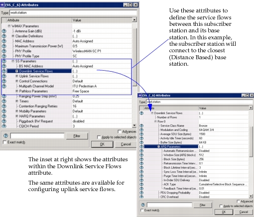
ARQ configuration is included in the service flow definition. By default, ARQ is disabled. To enable ARQ, set the WiMAX Parameters > SS Parameters > Downlink/Uplink Service Flows > ARQ Parameters > Automatic Retransmission Request attribute to Enabled and make sure that the Efficiency Mode attribute (on the WiMAX configuration object) is set to any level except Efficiency Enabled. This enables ARQ with the default configuration settings. To customize the configuration, you can modify the other parameters in the ARQ Parameters attribute on the subscriber node.
The PDU Dropping Probability attribute can be configured to model PHY-layer losses on a per-connection basis when the efficiency mode is set to Framing Module Enabled. In the Physical Layer Enabled efficiency mode, the packets are dropped based on the physical layer effects. The ARQ module reacts to packet losses by retransmitting the PDUs.
Similar to ARQ, HARQ is used per WiMAX service flow. It can be activated by setting the WiMAX Parameters > SS Parameters > Uplink-Downlink Service Flows > HARQ Enabled attribute on an SS node. HARQ parameters are shared by all service flows on the node. They are configured under WiMAX Parameters > SS Parameters > Uplink (Downlink) Service Flows > HARQ Parameters. These parameters are used only by services flows that use HARQ.
Configuring Adaptive Modulation and Coding (AMC)
AMC can be enabled or disabled for each service flow (it is enabled by default), as described in Procedure 117. To model AMC, the WiMAX Efficiency Mode must be set to Mobility and Ranging Enabled.
Procedure 117: Configuring AMC in a WiMAX Network
-
On the subscriber stations, set the Modulation and Coding attribute (WiMAX Parameters > SS Parameters > Downlink/Uplink Service Flows > Modulation and Coding) to Adaptive for all services flows that will use AMC.
-
On the WiMAX Configuration Object, configure the thresholds used by AMC in the AMC Profile Sets Definitions attribute. The profile sets defined in this attribute are used to set the AMC thresholds on the base stations.
-
On the base stations, configure the uplink and downlink AMC thresholds by choosing one of the profile sets (defined in the previous step) for each of the following attributes:
- DL AMC Profile Set
- UL AMC Profile Set
End of Procedure 117
Procedure 118 describes how to configure profile sets for AMC in the WiMAX configuration object.
Procedure 118: Configuring AMC Profile Sets
-
Right-click on the WiMAX configuration object and select Edit Attributes.
-
Expand the AMC Profile Sets Definitions attribute.
-
Click in the Value column next to UL Profile Sets to configure uplink thresholds. To configure downlink thresholds, click next to DL Profile Sets.
-
Add one or more rows to the table, according to the number of profile sets you want to create.
-
For each new profile set, double-click in the Profile Set Information column and configure the Mandatory Exit Threshold and Minimum Entry Threshold attributes.
When configuring the thresholds, make sure that for any three profiles with increasing Mandatory Exit Thresholds, the following conditions are true. For all conditions, Profile A has the lowest Mandatory Exit threshold and Profile C has the highest Mandatory Exit Threshold.
- The Mandatory Exit Threshold for Profile A is less than or equal to the Mandatory Exit Threshold for Profile B
- The Minimum Entry Threshold for Profile A is less than the Minimum Entry Threshold for Profile B
- Mandatory Exit Threshold for Profile C is greater than or equal to the Minimum Entry Threshold for Profile A
- Bits per symbol * coding for Profile A is less than or equal to the bits per symbol * coding for Profile B
- Mandatory Exit Threshold for Profile A is less than the Minimum Entry Threshold for Profile A
End of Procedure 118
Procedure 119 describes how to configure a base station to use an AMC profile set.
Procedure 119: Referencing AMC Profile Sets on a Base Station
-
Right-click the base station and select Edit Attributes from the pop-up menu.
-
Expand the WiMAX Parameters > BS Parameters attribute.
-
For the DL AMC Profile Set attribute, choose one of the available profile sets.
-
For the UL AMC Profile Set attribute, choose one of the available profile sets.
End of Procedure 119
Assigning Traffic to Service Classes
The service flows between subscriber and base station nodes can be configured to use a particular service class.
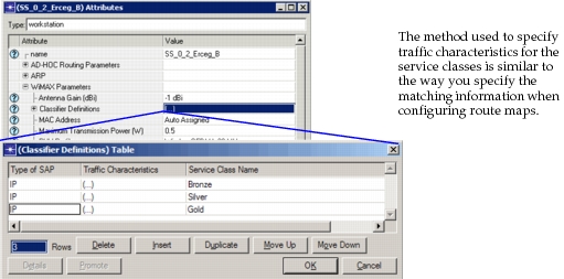
You can assign traffic to service classes in the WiMAX Parameters > Classifier Definitions attribute on subscriber and base station nodes. The assignments specified in this attribute apply to traffic sent from the station. In other words, the Classifier Definitions attribute on subscriber stations applies to traffic in the uplink direction (to the base station) whereas the Classifier Definitions attribute on base stations applies to traffic in the downlink direction (to the subscriber station).
When configuring classifier definitions, you use a match condition to specify the type of traffic that should be assigned to a particular service class. You can use the following characteristics to classify traffic: type of service, source address, destination address, source port, and destination port. Any traffic that is not explicitly assigned to a service class is sent using Best Effort service.
By default, the WiMAX node models have no classifier definitions configured on them, which means that all traffic would use the default best effort connection (System Default connection).
Figure 640: Configuring Traffic to Use a Particular Service Class
Configuring Physical Layer Parameters
If you want to include physical layer effects in the network model, you need to configure the following parameters on subscriber and base station nodes:
- Transmission Power
- Pathloss Parameters (subscriber stations only)
- Multipath Channel Model (subscriber stations only)
- PermBase (base stations only)
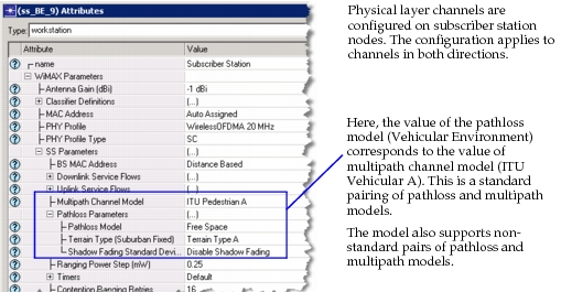
The model assumes that the physical channel from the subscriber station to the base station has the same properties as the reverse channel that goes from the base station to the subscriber station. Therefore, both channels are configured by the Pathloss Parameters and Multipath Channel Model attributes on the subscriber station.
The Pathloss Parameters attribute and Multipath Channel Model attributes are configured and implemented separately. Although the model includes corresponding values for these attributes, you do not have to use corresponding values. This gives you the flexibility to experiment with non-standard pairs of multipath and pathloss models.
Figure 641: Configuring Physical Layer Channels
Configuring Mobility
To model mobility in WiMAX networks, configure the network as follows:
- WiMAX efficiency mode—The WiMAX efficiency mode must be set to Mobility and Ranging Enabled.
- Handover and scanning—Attributes that control handovers and scanning are configured under the WiMAX Parameters > SS Parameters > Mobility Parameters attribute on subscriber stations and under the WiMAX Parameters > BS Parameters > Mobility Parameters attribute on base station nodes.
- ASN (access service network) anchored mobility—The ASN Gateway IP Address attribute (WiMAX Parameters > BS Parameters > ASN Gateway IP Address) on base station nodes specifies the address of the ASN Gateway. For information on how to configure ASN anchored mobility, see Procedure 120.
- Mobile IPv4—On base station node models, each WiMAX interface belongs to a unique IP subnet. To facilitate Layer-3 handoff between base station interfaces, mobile IPv4 must be configured on the base stations (BS) and mobile stations (MS). For information on how to do this, see Procedure 121.
ASN anchored mobility is implemented using GRE tunnels to route traffic from the base station nodes to the ASN. The following features of ASN anchored mobility are supported:
- Transfer of service flows from the mobile stations
- Transfer of data queues
Note that each base station can use only one ASN gateway and that a single GRE tunnel to the ASN is used for all mobile stations connected to the base station. Layer-3 connectivity is maintained for handovers that occur through a single ASN only—if handovers occur between base stations that use different ASN gateways, Layer-3 connectivity is not maintained.
Figure 642: Configuring ASN Anchored Mobility in a WiMAX Network
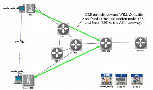
Procedure 120 describes how to set up ASN anchored mobility in a WiMAX network.
Procedure 120: Configuring ASN Anchored Mobility
-
Set up GRE tunnels between the ASN gateway and each of the base stations that use it. When configuring the GRE tunnels, note that:
- Two tunnels, one in each direction, are needed for each base station that connects to the ASN gateway.
- The interfaces used as end-points of the tunnel must have manually configured IP addresses. Tip: You can simplify ASN configuration by setting up the network so that the ASN uses the same link to access all base stations (see Figure 642).
- Any type of interface can be used for the tunnel address—you do not need to use a physical interface.
-
On each base station that connects to the ASN, configure the ASN Gateway IP Address attribute (WiMAX Parameters > BS Parameters > ASN Gateway IP Address). Use this attribute to specify the IP address of the ASN gateway; any IP address configured on the ASN gateway can be used.
-
Manually assign IP addresses to the WiMAX interfaces of all base stations in the network. Make sure that all of these addresses are in the same IP subnet.
-
Use route maps to configure an uplink traffic policy on the base station nodes that forwards all WiMAX traffic to the GRE tunnel. The route map should be configured to send all traffic that is received on any of the base station's WiMAX interfaces to the GRE tunnel without making any changes to the forwarded traffic.
End of Procedure 120
Procedure 121 describes how to configure Mobile IPv4 to support WiMAX mobility.
Procedure 121: Configuring Mobile IPv4 for WiMAX Mobility Support
-
Configure the base station nodes to support mobile IPv4.
1.1 Manually assign IP addresses to the WiMAX interfaces of all base stations that need to support mobility (and hence mobile IPv4). The IP interface for WiMAX usually has an MTU of 1500, which can be useful when trying to identify WiMAX interfaces on a BS node.
1.2 Specify the IP interface name (that runs WiMAX). To do this, configure the IP > Mobile IP Router Parameters > Mobile IPv4 > Interface Information > Interface Name attribute. For example, in wimax_bs_router_adv the interface name is "IF32".
1.3 Specify the mobile IPv4 agent type for the WiMAX IP interfaces. To do this configure the IP > Mobile IP Router Parameters > Mobile IPv4 > Interface Information > Agent Type attribute. The recommended value of this attribute is Home Agent/Foreign Agent.
-
Configure the subscriber station nodes to support mobile IPv4.
2.1 Specify the home agent. To do this, set the Home Agent IP Address attribute (IP > Mobile IP Host Parameters > Home Agent IP Address) on the mobile station to the IP address of one of the base stations configured in step 1.1.
2.2 If the mobile station will start the simulation in a network other than its home network, give the mobile station an IP address that matches the IP subnet of its home agent.
End of Procedure 121