Configuring Group and Hierarchy Information
A network’s group and hierarchy information is configured on a node-by-node basis. The model’s addressing scheme parallels the actual addressing scheme used in PNNI by modeling physical level node IDs, logical group node (LGN) IDs, and peer group IDs. The values specified for a node’s ATM Address, Level ID, and Group ID attributes determine its physical level node ID, LGN ID, and peer group ID. The rules used to derive a node’s addressing information from its attributes are listed in the following table.
Table 179: Derivation Rules Used to Generate Node and Peer Group IDs
| Physical Level Node ID | <level[n]_level_id>. <level[n-1]_level_id>. … .<level[0]_level_id>.<level[n]_group_id>. <level[n-1]_group_id>. … .<level[0]_group_id>.<atm_address> |
| LGN ID | <level [n]_level_id>.<level [n-1]_level_id>. … . <current_level_id>.<level [n]_group_id>.<level [n-1]_group_id>. … . <current_group_id>.<atm_address> |
| Peer Group ID | <level [n]_level_id>.<level [n-1]_level_id>. … . <current_level_id>.<level [n]_group_id>.<level [n-1]_group_id>.....<current_group_id> |
Figure 437: Hierarchical Addresses
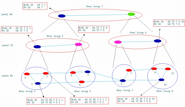
The following table lists the node and group IDs for Node 2 in Figure 437 (solid blue), whose ATM address is 1.
Table 180: Node and Group IDs for Node 1
| Level | Node ID | Peer Group ID |
|---|---|---|
| 80 | 64.72.80.7.5.1.1 | 64.72.80.7.5.1 |
| 72 | 64.72.7.5.1 | 64.72.7.5 |
| 64 | 64.7.1 | 64.7 |
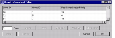
Figure 438: Level Information for Node 1
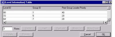
To define groups, configure each node in the group with the same Level ID and Group ID settings. Each node in the group, not just the peer group leader node, must be configured with all of its hierarchical information. Figure 439 shows the Level Information Table for Node 3. Note that the Level ID and Group ID settings are identical to those of Node 1, shown in Figure 438.
Figure 439: Level Information for Node 3