Local Attributes: PNNI
Every NNI node (ATM switch) has an attribute called ATM > ATM Routing Parameters > PNNI Parameters, which is used to specify PNNI configuration parameters. Note that workstations, servers, and routers are not NNI nodes and do not have the PNNI Parameters attribute.
Figure 429: Default Settings for PNNI Parameters Attribute
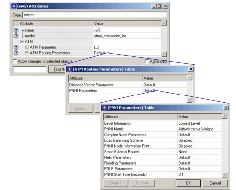
The ATM PNNI Parameters attribute consists of several sub-attributes, which can be viewed by double-clicking in the Value field (or by selecting Edit… from the Value field pull-down menu).
Some of the important PNNI model attributes are:
-
Level Information. This compound attribute specifies hierarchy information for nodes using PNNI. The model uses the level information to configure the Physical Level Node IDs, Logical Group Node IDs, and Peer Group IDs that the PNNI protocol requires to make routing decisions. The default setting configures all nodes to be at the lowest level.
To configure the Level Information attribute, double-click in the Value column to open the Level Information Table dialog box. Set the number of rows to be equal to the number of levels the node is represented in. There should be one row for each level including the physical level. For example, if there are 4 levels (the physical level + 3 logical levels) the node is represented in, then the table should have 4 rows. The three Level Information parameters are described below:
-
Level ID. This attribute specifies the node’s level as an integer value from 0 to 103, inclusive. Each row corresponds to a unique hierarchical level that is identified by the Level ID. The default value for the physical level, which is the level depicted when you build your network topology, is 80. The physical layer is denoted by the Level ID with the highest value, while higher hierarchical levels are denoted by lower values.
-
Group ID. This attribute specifies which group the node belongs to, at the specified level. The value can be any integer from 1 to 999, inclusive.
-
Peer Group Leader Priority. This attribute specifies a priority value that is compared to other nodes in the peer group. The node with the highest non-zero leadership priority is selected as the peer group leader. The peer group leader is the node through which all nodes in the group are visible to higher levels and groups. If the peer group leader node fails, the hierarchy above it collapses, and the other nodes in the group are no longer visible to the rest of the network.
If there are multiple nodes in the peer group with the same Peer Group Leader priority, the node with the higher ATM address is chosen to be peer group leader.
If all nodes in the peer group have a zero priority, there is no peer group leader in that group and it is not represented at any higher logical levels.
By default, all nodes have a zero priority, which means that a network with default attribute settings, will be a flat PNNI network, and all nodes belong to the same peer group.
For additional information on how to set up groups and hierarchies in your network model, see Configuring Group and Hierarchy Information.
-
-
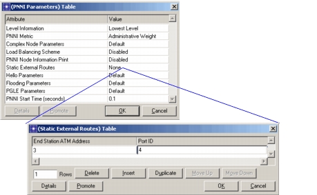
Static External Routes. Inter-routing between NNI domains is accomplished by configuring external static routes. If you are inter-connecting two or more NNI domains, be sure to specify Static External Routes on all border nodes, which are the nodes that connect to other domains. To define external routes to NNI domains, add a row for each NNI domain, specifying the destination ATM address and the output port number for each domain.
Figure 430: Specifying External Routes
-
PNNI Metric. This attribute specifies the metric used to select the shortest path route to the destination. It is used by the ingress NNI node (entry border node) of every peer group to calculate the route through that peer group to reach the destination. One of the following metrics can be specified to determine the shortest path route:
- Administrative Weight (AW)
- Cell Transfer Delay (CTD)
- Cell Delay Variation (CDV)
Administrative Weight is the default PNNI metric.
For CBR and VBR traffic, the route selected must also meet the cell transfer delay and cell delay variation constraints specified by the traffic contract (a rule that applies to all PNNI metrics). Because these CTD and CDV constraints must be met, it is possible that when Administrative Weight is specified as the PNNI metric, the selected route may not have the lowest administrative weight value.
For CBR and VBR traffic, if the shortest path computed using the administrative weights metric does not satisfy the CTD or CDV constraint, a new path is computed using the CTD metric. If this path does not satisfy the CDV constraint, a third path is computed using the CDV metric. If this path does not satisfy the CTD constraint, no route is found to the destination. A similar procedure applies if either CTD or CDV is selected as the metric.
-
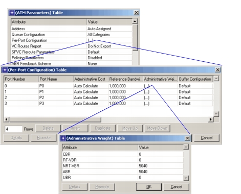
Administrative Weight. This per-port per-category attribute specifies the cost incurred when traversing the link on that port for the particular category. It is specified in the Per-Port Configuration attribute in the ATM Parameters attribute (see Figure 431).
Figure 431: Specifying Administrative Weight on a Port
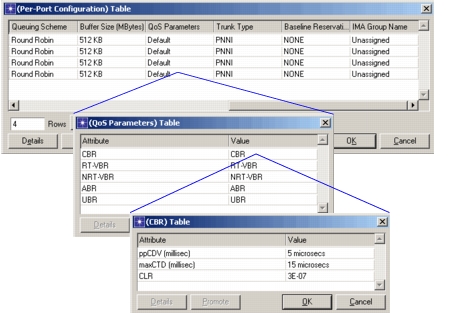
- maxCTD and ppCDV. Cell transfer delays (maxCTD) and cell delay variations (ppCDV) are node attributes, which are specified in a node’s QoS Parameters Table on a per-port per-category basis.
Figure 432: Specifying CTD and CDV on a Node
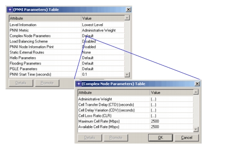
- Complex Node Parameters. This attribute governs the cost of traversal of the logical node in the PNNI hierarchy. The complex node parameters are shown in Figure 433.
Figure 433: Complex Node Parameters
-
Load Balancing Scheme. This attribute determines the type of load balancing scheme used to differentiate between equal cost paths to a destination. The three load balancing options are Maximum Bandwidth, Random Uniform, or Disabled.
- Maximum Bandwidth. This approach selects the maximum bandwidth link at every node when walking backwards from the destination towards the source when building the shortest path tree.
- Random Uniform. This approach selects a random link at a node based on a uniform distribution when walking backwards from the destination towards the source when building the shortest path tree.
- Disabled. No load balancing takes place on this node if you specify Disabled. The same path is chosen for every call between a source and destination until there is not enough bandwidth to support the call. If GCAC fails on that route, a new route will be chosen.
-
PNNI Node Information Print. This attribute specifies when to print out the topology database of the node to the simulation log. This attribute is used only by Explicit PNNI.
-
Aggregation Token. This link attribute specifies link aggregation. If peer groups are connected by several links at the physical layer, you can specify that these links are represented by an aggregated link at the logical level. To specify that two or more links are aggregated at the logical level, specify the same Aggregation Token value for each link. Links with different aggregation tokens will not be aggregated. By default, all links are assigned the same aggregation token. Link aggregation is performed on all logical horizontal links and induced uplinks.