Model Attributes: OSPF
All nodes that can run the OSPF protocol have an IP Routing Protocols > OSPF Parameters attribute, to specify OSPFv2 configuration parameters, and IP Routing Protocols > OSPFv3 Parameters, to specify OSPFv3 configuration parameters. The main OSPF attributes are described below.
Process Parameters
This compound attribute configures OSPF parameters on a per-process basis. The configurable attributes that affect simulation results are described below.
Figure 417: Process Parameters for OSPF
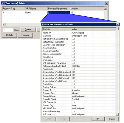
Start Time. This attribute specifies a distribution for the OSPF protocol’s start time on all interfaces of the router.
External Route Information. This attribute specifies static routing information for areas of the network that do not use a dynamic routing protocol. You should not specify External Route Information for nodes that are accessible through dynamic routing protocols.
Area Summarization. This attribute specifies route aggregation on border routers of an area. The routes specified by the address range are aggregated into single “summary” route. IPv4 address ranges are specified as a (network address, mask) pair whereas IPv6 address ranges are specified as a (network address, prefix length) pair. This route can be advertised to or hidden from other areas by selecting the appropriate Status. If no instructions are specified for an address range (that is, if the range does not appear in the Area Summarization Table), all applicable advertisements are forwarded individually.
Figure 418: Area Summarization Table
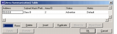
Address Summarization. This attribute is used to configure addresses/mask to summarize a range of addresses that get injected from one OSPF area to another.
Virtual Links. This attribute specifies a list of virtual links connecting this router to other area border routers (ABRs). This attribute must be configured on both routers (one at each end) of the virtual link.
-
Neighbor Router ID. This attribute specifies the Router ID of the ABR at the other end of the virtual link. You can find (or specify) a router’s ID in the IP Routing Parameters attribute.
-
Transit Area. This attribute specifies the Area ID of the transit area for the virtual link. The transit area must be common to both ABRs and cannot be the backbone area (0.0.0.0).
The remaining Virtual Links attributes allow you to specify OSPF timers for the link. For descriptions of these timers, see the corresponding descriptions of the IP Routing Protocols > OSPF Parameters > Interface Information > Timers attribute above.
SPF Calculation Parameters. This attribute specifies parameters that determine how and when routing table calculations are done. A periodic or LSA-driven style can be used. In either case, routing table calculations are performed only if the router has received an LSA update. When the periodic style is used, routing table calculations occur at regular intervals. When the LSA-driven style is used, the router does routing table calculations a configurable amount of time after it receives a new LSA. When SPF is periodic, use the Hold Time sub-attribute to configure the period between two calculations. When the SPF is LSA-driven, use the Delay sub-attribute to configure the period between the LSA arrival and the routing calculation and use the Hold time sub-attribute to specify the minimum delay between two calculations.
Reference Bandwidth. This attribute specifies the reference bandwidth used to calculate interface cost when the IP Routing Protocols > OSPF Parameters > Interface Information > Cost attribute is set to Auto Calculate.
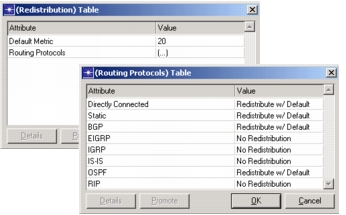
Redistribution. This attribute specifies whether routes learned through other routing protocols are advertised by OSPF. If set to Disabled, this router advertises only OSPF routes whereas the Enabled setting advertises all known routes. Alternatively, you can select Edit... to specify that routes derived from certain routing protocols are advertised, while all others are not.
Figure 419: Specifying OSPF Route Redistribution
Interface Information
This compound attribute specifies OSPF configuration for each IP interface. Each router interface is specified in the Name column. The Status column indicates whether OSPF is enabled on an interface. Although you cannot modify the OSPF status of an interface here, you can quickly identify which interfaces have OSPF enabled. The main Interface Information attributes are described below:
Figure 420: OSPF Interface Information
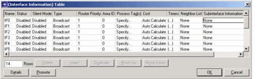
- Type. This attribute specifies the type of technology—Broadcast, Point To Point, Non-Broadcast, Point-to-Multipoint, or MANET—used to transmit packets over a given interface. Generally, the pre-configured values chosen by the model library can be left in place.
Note: The MANET interface type can be configured in OSPFv3 networks only.
WARNING: When configuring MANET in your OSPFv3 network model, disable Wireless LAN > Wireless LAN Parameters > Access Point Functionality on all Wireless LAN interfaces or your discrete event simulation will not run.
-
Router Priority. This attribute specifies the router priority used to perform designated router (DR) election. The router with the highest priority number is chosen as the DR.
-
Area ID. This attribute specifies the area the interface belongs to. Interfaces with the same Area ID belong to the same area. The default setting for this attribute is 0, which means that all routers belong to the backbone area.
-
Process Tag. This attribute specifies the OSPF process(es) that this interface belongs to. Processes must be configured in the Process Parameters attribute before they can be applied to an interface in this using this attribute.
-
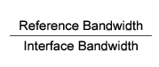
Cost. This attribute specifies the cost of sending a packet on the interface. If you do not specify a cost, selecting Auto Calculate will set a cost equal to the greater of 1 or:
-
Timers. This compound attribute specifies the following OSPF timers:
Figure 421: OSPF Timers
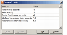
- Hello Interval. Time between Hello packets sent by the router on this interface. This value should be the same for all interfaces connected to a common network. The default value is 10 seconds; in a MANET network, the recommended value is 2 seconds.
- Hello Jitter (%). Percentage of the Hello Interval to jitter OSPF hello message send times. Hello messages will be sent between Hello Interval and Hello Interval * (1 + (Hello Jitter / 100)) seconds apart.
- Router Dead Interval. Time after which, if a neighboring router’s Hello messages are not seen, it is considered inactive. It should typically be set to some multiple of the Hello Interval, and should be the same for all interfaces attached to a common network. The default value is 40 seconds; in a MANET network, the recommended value is 6 seconds.
- Interface Transmission Delay. The estimated time it takes to transmit a link state advertisement (LSA) packet over this interface. This value is used to age an LSA prior to transmission on an interface. The default value is 1 second.
- Retransmission Interval. Time (in seconds) between LSA retransmissions for adjacencies belonging to this interface. The default value is 5 seconds.
-
MANET Parameters. This compound attribute specifies the following MANET timers:
- Full Hello Frequency—specifies the frequency of a “full hello” message, which carries the bidirectional neighborhood of a node. Specifying a lower frequency reduces the overhead created due to hello messages. The recommended value is “every third.”
- Hello Repeat Count—specifies the number of consecutive “partial hello” messages in which the change of status of a node's neighbor is persistently sent. This mechanism ensures that the receiver gets the up-to-date two-hop neighbor information in the absence of a full hello. The recommended value is “three times.”
- Adjacency Connectivity—specifies how a node establishes adjacency with neighboring MANET designated routers (MDRs). When set to “Uniconnected”, Backup MDRs will not be selected and each MDR-other node is guaranteed to be adjacent with only one MDR parent. A uniconnected adjacency graph reduces protocol overhead, but can induce instability. When set to “Uniconnected with BMDRs”, Backup MDRs will be selected, but each MDR-other node is still guaranteed to be adjacent to only one MDR parent. When set to “Biconnected”, MDR-other nodes can be adjacent to more than one MDR parent. A biconnected adjacency graph improves network stability at the expense of more overhead. The recommended value is “Biconnected.”
- MDR Constraint—A parameter internal to the MDR selection algorithm. Choosing a large value will decrease the number of MDRs, whereas choosing a small value will increase the number of MDRs. Choosing a value greater than 4 has no effect. The recommended value is “3.”
- LSA Forwarding—Determines which set of router links will be sent in LSAs when using OSPFv3 MANET. Possible values are:
- Backbone—Send only the backbone set of nodes
- Min Cost—Send the set of LSAs that will provide minimum-cost routes to all neighbors
- MDR Full—MDRs send full LSAs while other nodes send minimal set (backbone)
- Full—Send all LSAs
- Neighbor Acceptance Threshold—Number of consecutive hello messages received needed to transition a DOWN link to the INIT state.
- Allow Non-Flooding MDRs—If enabled, individual MDRs can declare themselves non-flooding MDRs if they believe the area around them is sufficiently covered by other MDRs. Non-flooding MDRs do not automatically flood LSAs back out an interface, but otherwise act as MDRs.
- BMDR Flood Timer (seconds)—Time to wait between when a BMDR receives a new LSA and when it floods it out the interface. During that time, if each neighbor has ACKed or flooded the LSA, the LSA will not be flooded by the BMDR. If the timer is set to “No BMDR Flooding”, BMDRs will never flood the LSAs.
-
Neighbor List. This attribute specifies the IP interface addresses (on the common network) of the neighboring routers. Used only for Non-Broadcast and Point-to-Multipoint interfaces.
Loopback Interfaces
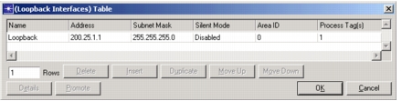
This attribute allows you to specify area IDs for the router’s loopback interfaces. From the Name pull-down menu, select a loopback interface (defined in the IP > IP Routing Parameters > Loopback Interfaces attribute). Setting the Name automatically sets the corresponding Address and Subnet Mask. Use the Area ID field to associate the loopback interface with a particular area and the Process Tag field to associate the interface with a particular process.
Figure 422: OSPF Loopback Interfaces