Saving and Loading Display Engine Configurations
This tutorial demonstrates how to:
- Connect 3D Network Visualizer to another 3D Network Visualizer Display Engine
- Change a display engine configuration
- Save display engine configurations
- Load display engine configurations in the Display Engine Configuration Editor
- Load multiple display engine configurations from the command line.
Connect a 3D Network Visualizer Display Engine
Note: To declutter the screen for screen captures, we have closed all of the information panels.
Note: This tutorial assumes that you have two computers, one for your 3D Network Visualizer application, and one for the remote display engine. You could run this tutorial on one computer if you have two monitors.
Procedure 212: Creating the display engine configurations
-
On computer 1, start 3D Network Visualizer.
-
Load
makland.mtf. -
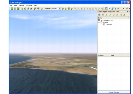
Choose View > Display Engine Configuration Editor Panel. The Display Engine Configuration Editor Panel opens. It shows one window and one channel for the 3D Network Visualizer window on the local computer (Figure 232).
Figure 232: Display Engine Configuration Editor Panel and default window
-
On computer 2, start another copy of 3D Network Visualizer.
A 3D Network Visualizer display engine opens.
-
On computer 1, in the Display Engine Configuration Editor, click the Connect a Display Engine icon (
 ). The Connect to Display Engine dialog box opens.
-
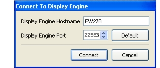
In the Display Engine Hostname box, replace
localhostwith the name of computer 2. (If you are using one computer with two monitors, leave the text aslocalhost.)Figure 233: Connect to Display Engine dialog box
-
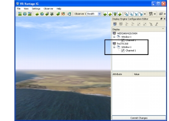
Click Connect. An entry for the remote display engine is added to the Display Engine Configuration Editor window. The remote display engine now displays the Makland terrain with the same view as the 3D Network Visualizer application.
Figure 234: Remote display engine connected
Save Display Engine Configurations
By default, the views in the 3D Network Visualizer window and the remote display engine window look exactly the same. So we will change the view in one of them so that when we load the display engine configurations later on, we can tell that each is different.
Procedure 213: Editing and saving the display engine configuration
-
Select Channel 1 of the remote display engine. Its attributes are displayed.
-
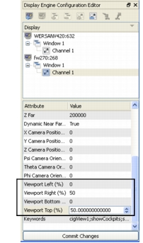
Change the value for the Viewport Right and Viewport Top attributes to 50.
Figure 235: Channel with changed viewports
-
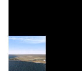
Click Commit Changes. The view of the terrain is now in the lower left quadrant of the display engine. (The full screen view of the terrain may also be visible until such time as the display engine refreshes.)
Figure 236: Remote display engine view after changing configuration
-
Select the display engine on the 3D Network Visualizer application (in this example, WERSANV420).
-
Click the Save Display Engine Configuration icon (
 ). A save dialog box opens.
-
Call this configuration
mainwindow.dcx. -
Click Save.
-
Select the display engine on the remote display engine (in this example, fw270).
-
Click the Save Display Configuration icon. A save dialog box opens.
-
Call this configuration
remotedisplay.dcx. -
Click Save.
Load the Display Engine Configurations in the GUI
We now have two visually distinct display engine configurations. In this part of the tutorial, we simply load them into the two display engines to see that loading a display engine configuration changes the view in the window. This part of the tutorial also demonstrates that display engine configurations are not unique to a particular display engine and are not tied to one either. Any particular configuration can be loaded into any display engine.
Procedure 214: Loading the display engine configuration in the GUI
- Select the display engine on the 3D Network Visualizer application.
- Click the Load Display Engine Configuration icon (
 ). The Load Display Configuration dialog box opens.
- Select
remotedisplay.dcx. - Click Open. The window on the 3D Network Visualizer application now shows the terrain in the lower left quadrant. (You may need to press Space Bar to reset the observer.)
- Reload the
mainwindow.dcxconfiguration in the main window. - Try loading the two different configurations in the remote display engine.
Load Display Engine Configurations from the Command Line
As you have seen in the previous part of this tutorial, you can load display engine configurations for individual display engines through the GUI. However, you cannot load more than one at a time. If you have a complex set of display engines that you need to configure, loading them one at a time can be tedious. To load multiple display engine configurations, you must start 3D Network Visualizer from the command line.
You load multiple display engine configurations from the command line with the --dispSetting command line argument and the -W or --withDisplayEngine command-line argument. The syntax is:
set OP_3DNV_VISUALIZER_EXTRA_ARGS = --dispSetting masterdisplayConfigFile
   -W port@netAddress;remotedisplayConfigFile1 ....
   port@netAddress;remotedisplayConfigFileN
op_3dnv_launcher.exe
In this tutorial, we use the default port (22563). The netaddress for the remote display engine is the computer name (FW270). The display engine configuration files are mainwindow.dcx and remotedisplay.dcx.
So the command line to load the two display engine configurations that we created would be:
set OP_3DNV_VISUALIZER_EXTRA_ARGS = --dispSetting
   ../appData/settings/vantageIG/mainwindow.dcx
   -W 22563@FW270;../appData/settings/vantageIG/remotedisplay.dcx
op_3dnv_launcher.exe
Procedure 215: Loading the tutorial configurations from the command line
-
Open a command window.
-
Change directory to
./bin. -
Enter the command:
set OP_3DNV_VISUALIZER_EXTRA_ARGS = --dispSetting
   ../appData/settings/vantageIG/mainwindow.dcx
   -W 22563@FW270;../appData/settings/vantageIG/remotedisplay.dcx
op_3dnv_launcher.exe
3D Network Visualizer starts. The display engine configurations are visible in the main window and the remote display engine window.
-
Choose View > Display Engine Configuration Editor Panel. In the Display Engine Configuration Editor Panel, confirm that 3D Network Visualizer is connected to the remote display engine.