Animation Fundamentals
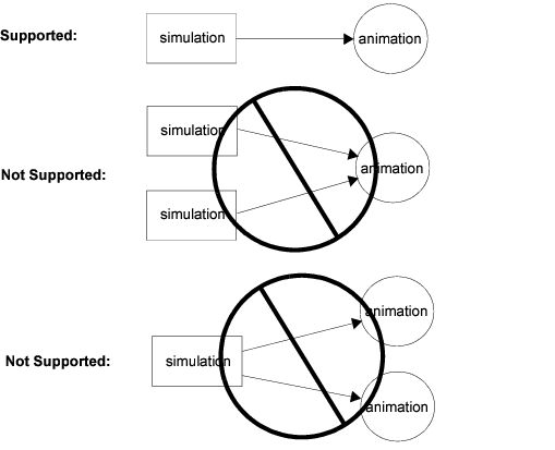
Animations can be produced and recorded during simulations. Animations and simulation runs have a one-to-one correspondence. Multiple simulation runs cannot contribute to a single animation. A simulation cannot produce more than one animation.
When a simulation run is initiated, the user specifies whether animation data will be recorded and how it will be routed. If “record animation” is specified, all animation data generated by a simulation run will be routed as indicated, contributing to a single animation. A simulation cannot change the routing of animation data while executing.
Figure 2: Simulation/Animation Relationships
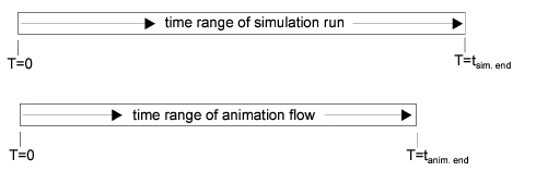
Animations depict dynamic simulation conditions. As simulation events occur at various points in simulation time, they generate animation data that is tagged with the associated simulation time. Thus, all animation data are associated with simulation time values. An animation time range always falls within the time range of the associated simulation run. Simulation runs have a beginning and an end in simulation time; likewise, their associated animations have beginnings and ends in simulation time. The first animation data generated by a simulation may begin later than T=0, and the last animation data generated by a simulation may occur well before the end of the run. However, animation data can never occur at negative times, or at times later than the end of the associated simulation run.
As a simulation producing an animation progresses, it typically generates animation data at a large number of irregularly spaced points in simulation, which are spread in small bursts throughout the simulation. Animation data depicting a simulation event is usually produced as soon after the event as possible, so that (synchronized viewing of animation data is possible (i.e., viewing the animation output of a simulation event shortly after it occurs, and before the simulation progresses to another event. The previous statements are usually true, but since users can generate custom animations through flexible Kernel Procedure invocations, it is possible to cluster the output of animation data into only a few large bursts that occur at the beginning, end, or some intermediate point in a simulation.)
Because animations are described by bursts of data that occur over a range of time, these bursts form a flow of data. The term animation flow refers to the sequence of animation data generated by a simulation run. As described later in this chapter, animation flows can be stored in a file, conveyed to another process using network protocols, or processed and displayed by a viewing program.
Figure 3: Comparison of Typical Simulation and Animation Flow Time Ranges
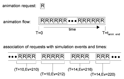
Bursts usually consist of animation data generated at the same simulation time. The fine-grain structure of bursts is a series of animation requests. Animation requests are the smallest units of animation data. Each animation request is associated with a single simulation time, a single simulation event, and a single source within the simulation (e.g., a specific process). Typically, animation flows will contain thousands of animation requests.
There are over forty types of animation requests supported by the Modeler system. New types of requests cannot be defined by users.
Simple animation requests describe a single graphical operation, such as drawing a line, and contain all the data required for the operation. A more complex animation request may describe a compound graphical operation, such as moving a symbol along a path. Such a request will depend on data contained in other requests--however, no matter how complex an animation request is, it never describes graphical operations associated with different simulation times or events.
Thus it is possible to segment an animation flow according to simulation times or events; such divisions always occur on request boundaries since these properties never change within a single animation request.
Figure 4: Animation Flows are Composed of Animation Requests
Animation flows can describe graphical operations performed within one or more abstract display regions called viewers. A viewer is a rectangular region with an internal coordinate system. Most animation requests are targeted to a particular viewer, as identified by a viewer ID contained within the request. Some administrative requests deal with animation-wide issues, and do not generate visible output in a particular viewer; these requests do not contain viewer IDs.
Viewers can be opened or closed by specific request types at any stage of an animation flow. However, viewers must be opened before requests can be targeted to them. Once a viewer has been closed, it cannot accept any further requests.
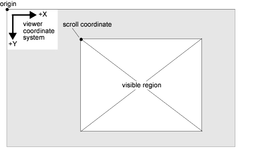
Animation requests specify graphical operations in terms of viewer coordinates. Each viewer has its own coordinate system, but the viewer coordinate systems share the following common properties:
- two-dimensional (X is the horizontal axis, Y is the vertical axis)
- origin is the upper-left corner
- positive X direction points right, positive Y direction points down
- only integral, non-negative coordinates are supported; the upper limit on coordinate values is 32,766
- coordinates are measured in units of pixels
- coordinate system extends beyond visible region of viewer
The request that opens a viewer specifies its location within the workspace coordinate system, and its initial size. Viewers may have intersections within the workspace, in which case the viewers that are opened later will initially overlap the viewers opened earlier. The size of a viewer determines the rectangular region of the viewer’s coordinate system that is visible, but it does not limit graphical operations from being performed outside of this visible region. The visible region of a viewer can be changed by scrolling the viewer via a specific request type. Due to the limitations of the viewer coordinate system, the visible region cannot be scrolled into the (X,Y) plane quadrants with negative coordinate values.
Figure 5: Animation Viewers within Workspace Coordinate System
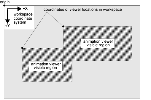
Figure 6: Animation Viewer Coordinate System
The abstract concept of a viewer is realized within the animation viewing program op_vuanim, which creates editor windows for each viewer. Viewer windows can be manipulated using the standard GUI operations for moving, resizing, scrolling, and circulating windows. These operations do not affect the animation being viewed, but change the presentation of the animation. Details of op_vuanim features appear later in this chapter.