Model Attributes: Advanced Wireless Package
The following attributes are available for configuring the advanced wireless package.
PHY attributes can be configured on individual nodes in the network, as shown in Local Attributes, or globally, using the PHY configuration utility node, shown in PHY Configuration Node.
Note: Global attributes will be used unless the PHY configuration utility node is set to "Use Node Settings" for a given attribute.
Local Attributes
Use the wrls_phy_station_adv node model to simulate wireless mobile nodes in your network, or use the wrls_phy_ppp_iface_adv node model to simulate a "modem" that can connect to an IP interface to add radio transmission capabilities. Set the configuration in the "PHY" attribute group or apply a global configuration profile, as set in the configuration node (see PHY Configuration Node).
Figure 3: Advanced Wireless Package Local Attributes
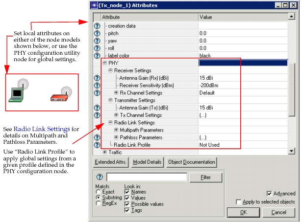
Notice that you can define the Pathloss Parameters locally on the node, and you can select the Multipath Parameters you want to use. This is described in the following section:
Radio Link Settings
Radio link settings can be configured on either the wireless nodes or as part of the settings of a Radio Link Profile on the PHY configuration utility node. The following topics are included in this section:
Multipath Parameters
The advanced wireless package supports ITU Multipath Channel models Pedestrian A, Pedestrian B, Vehicular A, and Vehicular B. You can add more multipath channel models in the PHY configuration node under the attribute "Multipath Channel Definitions", as described in Multipath Channel Definitions.
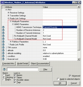
The Multipath Channel Model is selectable on each wireless node in the following attributes, shown in the figure below:
- PHY > Radio Link Settings > Multipath Parameters > Rx Multipath Channel Model and
- PHY > Radio Link Settings > Multipath Parameters > Tx Multipath Channel Model
Figure 4: Multipath Parameters on a Wireless Node
Multiple-Input/Multiple-Output (MIMO)
You can define the number of antennas and MIMO transmission technique used at each wireless node under the attribute PHY > Radio Link Settings > Multipath Parameters > MIMO Parameters, shown in the figure above. The number of transmit antennas and MIMO Transmission Technique at the transmitting node, together with the number of receiving antennas at the receiver node, will decide whether Single Input Single Output (SISO), transmit diversity, receive diversity or spatial multiplexing is used for communication between the two nodes. MIMO Parameters affect the SNR of the received signal in the presence of multipath fading. The advanced wireless package supports multi-codeword spatial multiplexing. A codeword is the MPDU sent by the client module to the PHY module for transmission. Using multi-codeword spatial multiplexing, two codewords having the same time and frequency information can be transmitted simultaneously. See Send Packets to the PHY Module (with Wireless Properties Specified) for details.
Pathloss Parameters
The following pathloss models are available. Relevant attributes are configurable under the PHY configuration utility node in Radio Link Profiles > Radio Link Settings > Pathloss Parameters for global settings or under PHY > Radio Link Settings > Pathloss Parameters on individual nodes.
Note: Certain pathloss models permit additional customization in the Model Arguments sub-attribute; however, many of the pathloss models are not configurable.
- Free space
- 3GPP-based models
- Suburban macrocell
- Urban macrocell
- Urban microcell
- COST321-based models
- Hata extension urban macrocell
- Hata extension suburban/rural macrocell
- Urban microcell based on Walfish-Ikegami
- ITU-R M.1225-based models
- Pedestrian
- Vehicular
- Indoor office
- ITU-R M.2135-based models
- Indoor Hotspot (InH)
- Urban Micro (UMi)
- Urban Macro (UMa)
- Suburban Macro (SMa)
- Rural Macro (RMa)
- Erceg suburban fixed
Shadow fading is also supported as log normal distribution model.
PHY Configuration Node
Use the PHY configuration utility node to configure one or more Radio Link Profiles, which you can apply to nodes in the network model. You can also create multipath channel definitions that can be selected by the nodes in the network.
Figure 5: Advanced Wireless Package Configuration Utility—Parameters
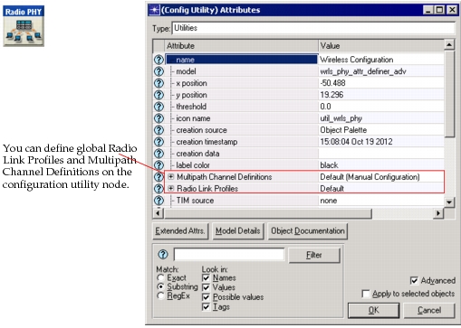
You can view descriptions of each attribute by clicking on the Details button in the Attributes dialog box.
Multipath Channel Definitions
You can define multipath channels on the PHY configuration utility node top-level attribute Multipath Channel Definitions. A multipath fading channel consists of a finite state Markov chain (FSMC), which captures the time evolution of the multipath channel and channel state dependent effective SNR mapping functions, which will be used to compute the effective SNR for a given channel state. The next state transition of the FSMC is governed by a transition probability matrix (TPM). The TPM and the channel state dependent effective SNR mapping functions together define the behavior of a multipath channel model.
You can specify the multipath parameters for a multipath channel model manually, or you can import the parameters from a file, as shown in the figure below.
Figure 6: Setting Multipath Parameters with the Advanced Wireless Package
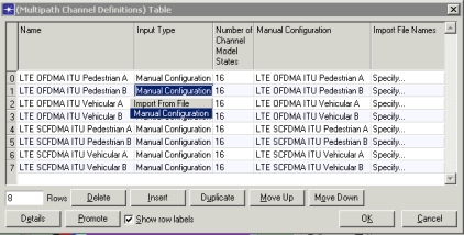
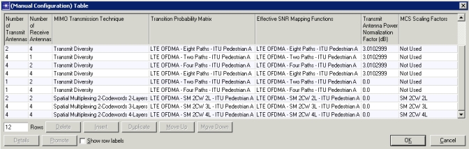
As part of manual configuration of the multipath channel model, for a given number of transmit and receive antennas and MIMO transmission technique, you can define a Transmission Probability Matrix (TPM) and effective SNR mapping functions as shown in the figure below. For details regarding specifying the multipath channel model to use on a node refer to Multipath Parameters.
Figure 7: Setting Multipath Parameters with the Advanced Wireless Package
Key Concept— If you create a directory containing custom files (for example, custom probability matrixes or Signal-to-Noise [SNR] mapping functions), you must add this directory to the model directories (mod_dirs) in Riverbed Modeler.
Custom probability matrix files and SNR mapping files must be formatted according to the supported type. For example, "mpath_tpm" (Transition Probability Matrix) or "mpath_snr" prefixes must be used in the file names, respectively. These files are text files with the extension gdf, which contain comma-separated values to indicate each row in the transition probability matrix or the coefficients of each polynomial for the SNR translation functions.