Composition of a SITL Model
A network model for use in a SITL simulation is largely identical to standard models. The only difference is the addition of a SITL gateway node used to represent the connection to external hardware. The simulation runs in real-time and exchanges packets with the external hardware via an Ethernet link.
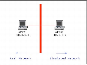
There are three basic configurations for SITL simulations. The simplest of these connects external hardware to a single simulation, as shown in the following figure. This configuration permits a real network to interact with a simulated one (for example, by sending ping messages to a simulated node and receiving responses).
Figure 1: Example Real–Sim Network
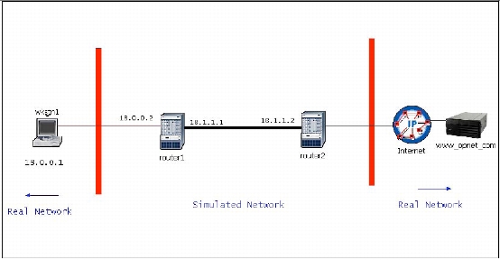
Another common configuration connects two pieces of external hardware together via a simulation (Figure 2). The simulation contains multiple gateways to connect to the different external ports. This allows, for example, real traffic to be routed through a simulated network so that the effect of network delays and protocol processing can be imposed on real network traffic.
Figure 2: Example Real–Sim–Real Network
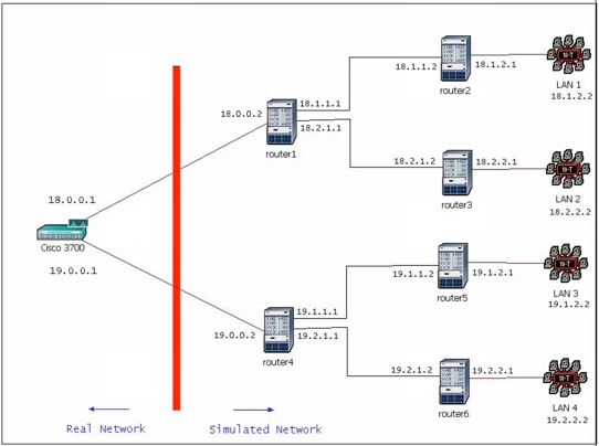
The third common configuration also uses multiple gateways in the simulation, this time to connect two simulated networks to external hardware (Figure 3). Using this configuration, you can send simulated traffic from one part of a simulation through a real network (such as a physical router) and back to another part of the simulation. An example usage of this configuration is to test the interoperability of OSPF on a real router with a simulated OSPF network.
Note: Sim–real–sim support in SITL is limited. The reason behind this limitation is that simulated packets created in the simulation, except the ones created by the SITL real-to-sim translation, have additional information associated with them that does not have a real equivalent. This additional information will not be included in real packets created by the SITL sim-to-real translation. When these real packets are fed back into the simulation, they will be lacking the additional information required by the other side of the simulation.
Figure 3: Example Sim–Real–Sim Network
Packet Processing
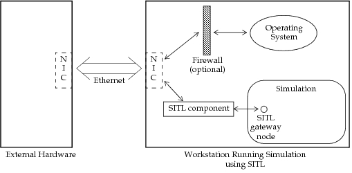
The following figure shows how packets are handled in a SITL simulation. Packets arriving on the network interface of the SITL computer are routed to the operating system through an optional firewall (used to block packets intended for the SITL simulation and other unwanted packets, thus reducing system overhead).
Simultaneously, a component of the SITL module routes packets intended for the SITL simulation directly from the network adapter to the simulation. The Simulation Kernel translates the entire packet, so that the gateway node sees complete Ethernet frames and passes them to the rest of the simulation.
Figure 4: Packet Pathways in a SITL Simulation
Supported Protocols
SITL simulations can use the following protocols supported by the standard models. (For details about support for each protocol, see Appendix B “Protocol Support” on page 34.)
- Ethernet
- ARP
- IPv4 headers are fully supported (except for fragmentation)
- IPv6 standard headers
- WLAN (802.11 b/g, data packets only)
- Higher layer protocol conversion (used in the real–sim and sim–real–sim configurations) is supported for:
- ICMP (ping)
- ICMP v6
- IGMP v2
- BGP
- OSPF v2
- RIP v1, v2
- TCP
- UDP
In addition, you can add support for your own protocols.
In the real–sim–real configuration, where real data is sent through a simulated network without need for conversion, virtually all application-layer protocols are supported. The simulation is used only as a transit network in which datagrams experience simulated network effects.